Corona Discharge
Overview
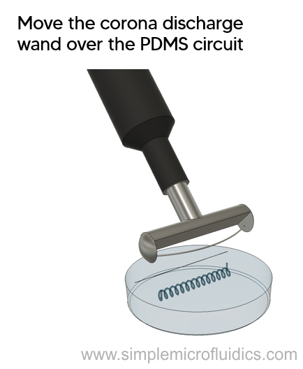
A source of corona discharge is run over PDMS circuit surface. This forms free radicals as the high energy electrons collide with the surface to break the bonds. Various functional groups (such as carbonyl, carboxyl, hydroperoxide, etc.) are formed which increase surface energy.
This method can also be used to bond the PDMS circuit to glass plates or to another PDMS component.
Technique
- Clean the PDMS circuit and make sure there is no dust/debris on the surface
- Take the corona discharge equipment and move it an inch over the surface of the PDMS circuit for 15-20 seconds
The modified PDMS circuit is ready to use.
Equipment
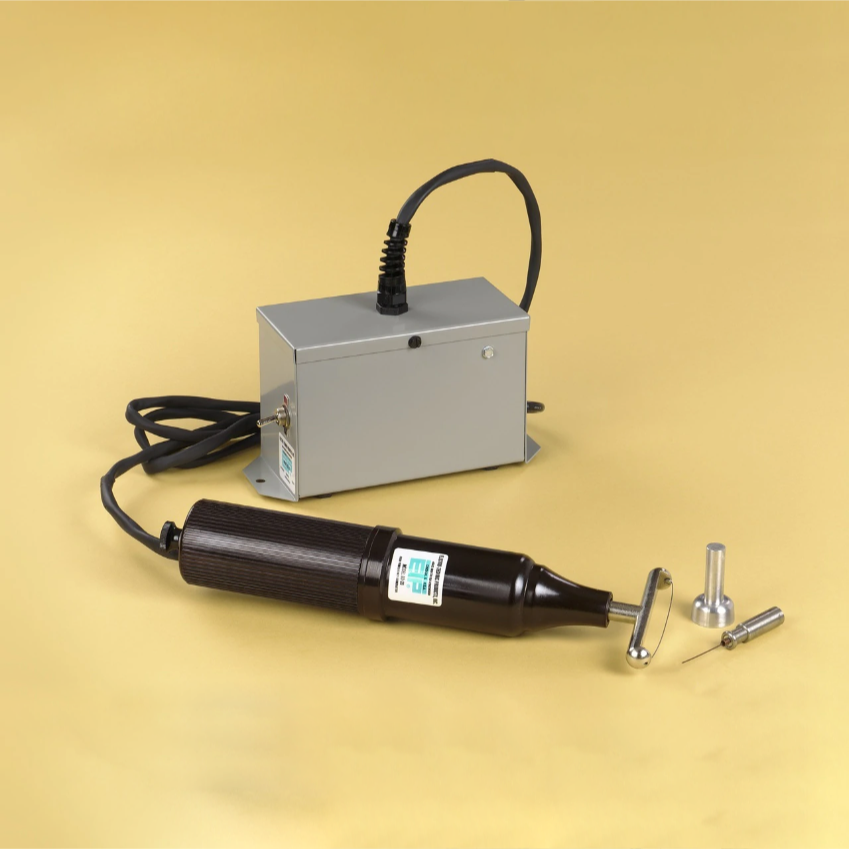
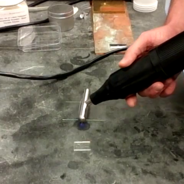
This video demonstrates how to use a plasma wand to oxidize the surface of the PDMS chip.
SolGel
TEOS
Overview
Safety note: Please check with your lab safety staff or supervisor before using this technique. TEOS is hazardous. Proceed at your own risk.
This technique can be used to prevent absorption of small hydrophobic molecules (such as drugs) into PDMS microfluidic circuits while maintaining other desirable properties like biocompatibility, transparency, and oxygen permeability. It works by filling the PDMS polymer matrix with silica nanoparticles through a TEOS immersion.
A 1 hour TEOS immersion maintains a nearly identical rate of oxygen transport as untreated PDMS. Chemicals which are readily absorbed by plain PDMS circuits such as camptothecin and kinase inhibitor PW12 can successfully be used for cell culture experiments in treated PDMS circuits.
Technique
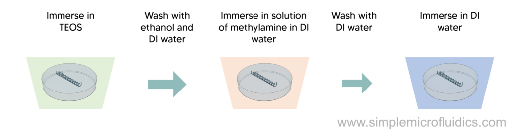
- Immerse the PDMS circuit in pure TEOS
- For the first 5 minutes, constantly agitate the immersion to prevent the circuits from sticking to the bottom
- Check the paper to get details on how long of an immersion is right for your application – a 1 hour immersion is a reasonable starting point
- After removing the circuit from the immersion, rinse with pure ethanol followed by DI water
- Immediately immerse in 4% (v/v) solution of methylamine in DI water for at least 15 hours (this prevents the formation of silica crystals which reduce transparency and make it harder to bond to glass slides)
- Remove the circuit and rinse with DI water
- Then immerse in DI water for another 24 hours changing the water twice during immersion (this will help maintain biocompatability)
- Dry in an oven at 80-95°C for 1 hour


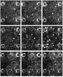
The source paper will walk you through the surface modification process and also provide quantitative data about the effects of TEOS immersion on oxygen permeability and cell motility from tested cell cultures.
Glass Coating
Overview
This method will coat the channels with a glass like layer to increases the chemical resistance of the channels and prevent swelling due to absorption of chemicals like toluene. Additionally the coating can be functionalized to produce the preferred wetting characteristics.
Technique
Safety note: Please check with your lab safety staff or supervisor before using this technique. TEOS is hazardous. Proceed at your own risk.
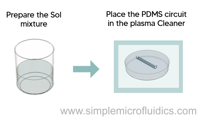
- Prepare the pre-converted sol mixture by adding TEOS, MTES, ethanol and 4.5 pH water adjusted with HCL in a 1:1:1:1 volumetric ratio
- To speed up the mixing process heat the mixture in a microwave for 10-20 seconds
- Place the homogenous mixture in an oven at 65°C for 12 hours to speed up pre-conversion
- Treat the PDMS circuit in a plasma cleaner to generate hydroxyl groups on the surface
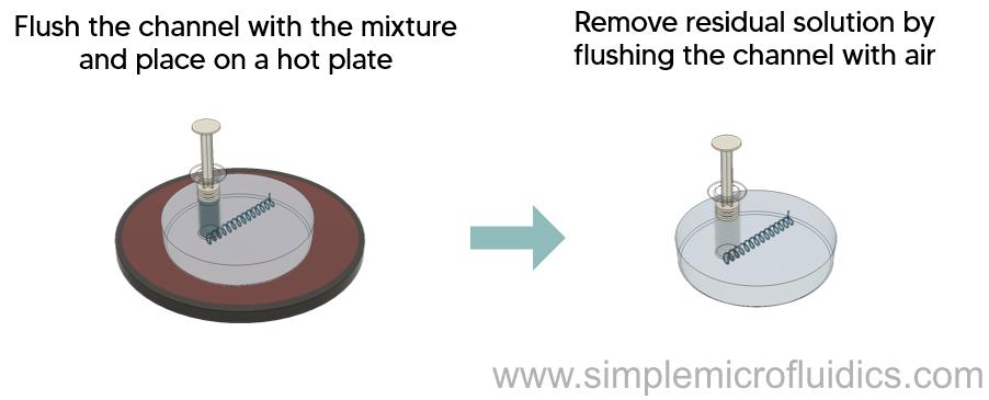
- Immediately flush the channels with the pre-converted sol mixture and place the device on a hot plate at 100°C for 10 seconds to initiate the gelation reaction
- Use air to flush out the remaining sol mixture
The coating is roughly 5-10µm thick – however the thickness can be controlled by increasing the conversion time of the mixture in the channel.


This paper details the coating protocol, and provides experimental data for changes in channel geometry, chemical resistance, as well as functionalization of the coating.
Boroslilicate glass coating
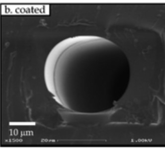
Overview
This technique coats the surface of the PDMS circuit channels with borosilicate glass. Borosilicate is a great material to use with chemicals and solvents – it also has good mechanical and thermal stability and a low curing temperature.
Technique
- Prepare the borosilicate active solution by adding 122 mmol of tetraethyl orthosilicate (TEOS) to 74 mmol of trimethoxyboroxine (TMB) in strictly closed and anhydrous conditions and allow to react at 22°C for 65 hours
- Add 80 mmol of formic acid and 624 mmol of dichloromethane and reflux the mixture for 3 hours. This will form a Si-O-Si network
- Distill the solution several times to remove the volatile non-reacted parts and then add 2-propanol to the solution
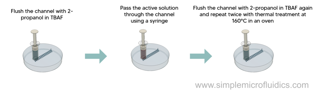
- Flush 2-propanol saturated with tetrabutylammonium fluoride (TBAF) through the channels for 2 minutes at 0.06 mL/min
- Pass the active solution through the channels for 2 minutes at 0.04 mL/min
- Apply a thermal treatment at 80°C under vacuum
- Flush the channels with the active solution for 10 minutes at 0.04 mL/min
- Repeat the previous step twice followed by thermal treatment at 160°C


Internal modification of poly(dimethylsiloxane) microchannels with a borosilicate glass coating.
J-B Orhan, V K Parashar, J Flueckiger, M A M Gijs
O2 Plasma
Plasma Cleaner
Overview
Oxygen plasma treatment on the surface of PDMS leads to the formation of polar functional groups (mainly SiOH) on the surface. This treatment is widely used to modify PDMS circuits and:
- Reduce hydrophobicity – water contact angle changes from ~112° to ~60° (Source)
- Reduce surface roughness from 3.6nm RMS to 0.9nm RMS for an exposure time of 500 s (Source)
- Increase young’s modulus from ~3.4MPa to ~130 MPa. (Source)
Technique
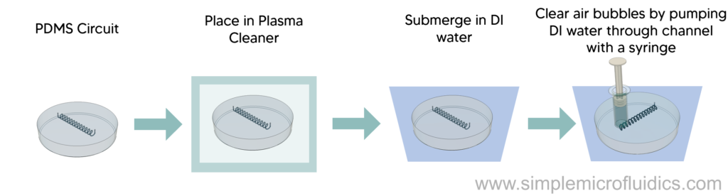
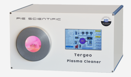
- Place the PDMS circuit in a commercial plasma cleaner and treat it for 300-500 seconds
- After treatment, remove the PDMS circuit and submerge it in a container filled with deionized water
- Make sure to fill the microchannels with DI water by using a syringe to pump DI water through the channels
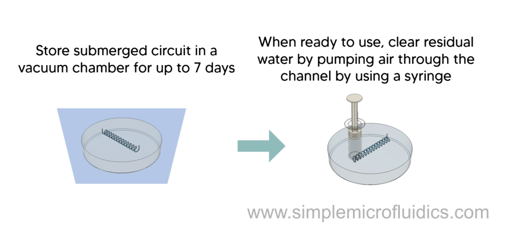
- You can store the submerged circuit in the vacuum chamber for up to 7 days as it removes all the air bubbles and ensures that the treated circuit is kept at a constant low temperature
- Remove the circuit and pump out the excess DI water from the channels before use

This paper provides details about oxygen plasma treatment – how long the treatment is effective for and how to store the circuit to increase the stability of the treatment.
Microwave
Overview
Safety note: Please check with your lab safety staff or supervisor before using this technique. Placing metal inside a microwave is dangerous and is a major safety hazard. Proceed at your own risk.
Technique
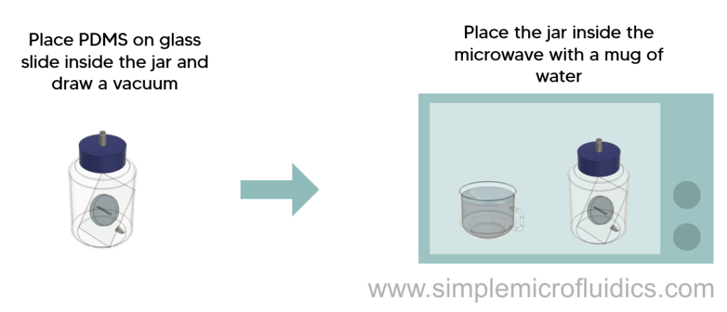
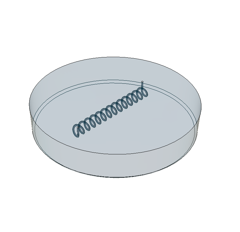
- Place a piece of aluminum foil inside a glass jar
- Place the PDMS circuit in the jar so that the glass slide acts as a barrier between the PDMS and the aluminum. This prevents sparks from the aluminum from burning the PDMS.
- Close the lid of the jar and draw a vacuum to reduce the pressure inside the jar to less than 0.8kPa. Higher pressures will make it difficult to spark the plasma.
- Place a glass of water in the microwave. This should absorb any excess energy and prevent damage to the microwave.
- Place the jar with the PDMS circuit in the microwave
- Set a timer for 30 seconds on the microwave, but stand-by the microwave to turn it off
- Plasma should start sparking within 5 to 10 seconds
- Once the plasma starts sparking, allow it to treat the PDMS for 10 to 15 seconds and then turn off the microwave
- Allow the jar to cool for at least 5 mins as the jar can get as hot as 100°C in just 15 seconds.
The surface modification properties of this technique should be somewhat similar to what is achieved using a plasma cleaner but this will vary depending on your setup.
Equipment


Microscope Slides
This will be bonded to your PDMS circuit so make sure to pick the right size
PDMS Circuit
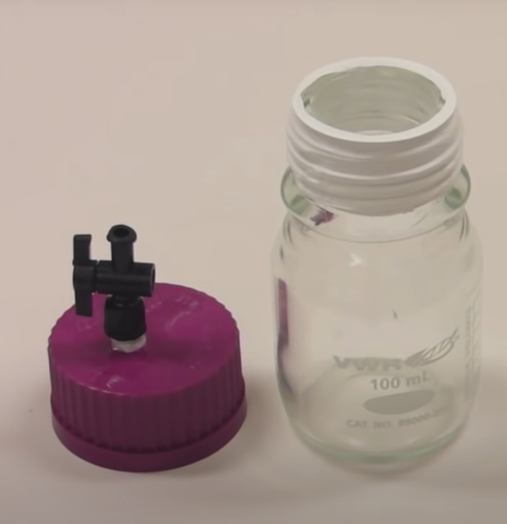
Glass jar with valve
Find a glass jar and drill a hole in the lid to install a ball valve in it, sealing the valve housing with liquid silicone. Wrap PTFE tape around the threads of the jar before closing the lid to ensure no leaks.
Don’t forget to double check that your PDMS circuit + glass slide will fit in the glass jar you use.


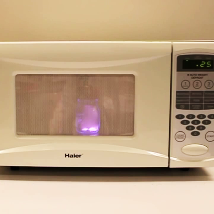
For labs that don’t have access to a dedicated plasma cleaner, this video from MIT demonstrates plasma treatment of PDMS microfluidic circuits using a household microwave oven.
Surfactant In-molding
Overview
This method is a one-step in-mold process that uses a layer of non ionic surfactants to render the PDMS surface hydrophilic in situ. The exposure of the pre-polymer to the surfactant during the vulcanization process entraps the surfactant molecules through adsorption, hydrophobic binding, and/or entanglement at the PDMS interface.
Polyoxyethylene dodecanol also known as Brij-35, Tween-20 and a-Wet are some of the commonly used surfactants for fast and effective surface modification of microchannels.
An easy approach to using non ionic surfactants is by using soft lithography with masks made by xurography to fabricate the microfluidic channels. Xurography is a prototyping technique that employs a knife plotter to structure thin foils onto which the prepolymer is poured.
Technique
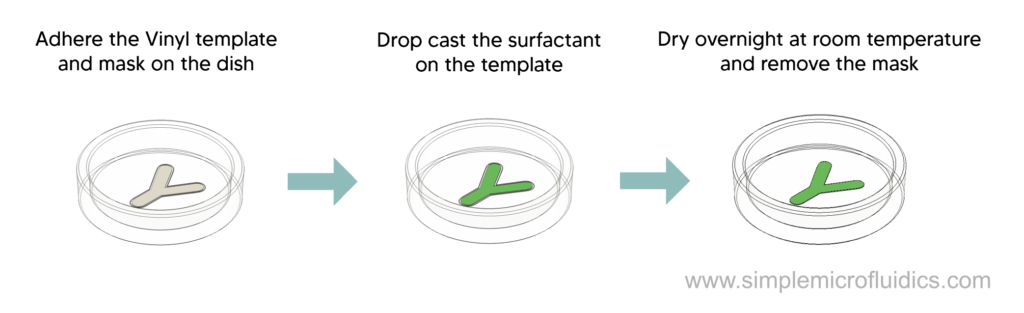
- Design and cut a template of the microfluidic channel from Self Adhesive Vinyl Film by using a blade cutter
- Lift the template and adhere them to clean polystyrene dishes
- Make vinyl masks 0.1 mm wider than the microfluidic template and adhere around the template, leaving space between the template and the mask
- Drop cast 30 μl of 10% solution (wt/v in IPA) of a-Wet over the vinyl template and let it dry overnight at room temperature
- Remove the outer vinyl masks
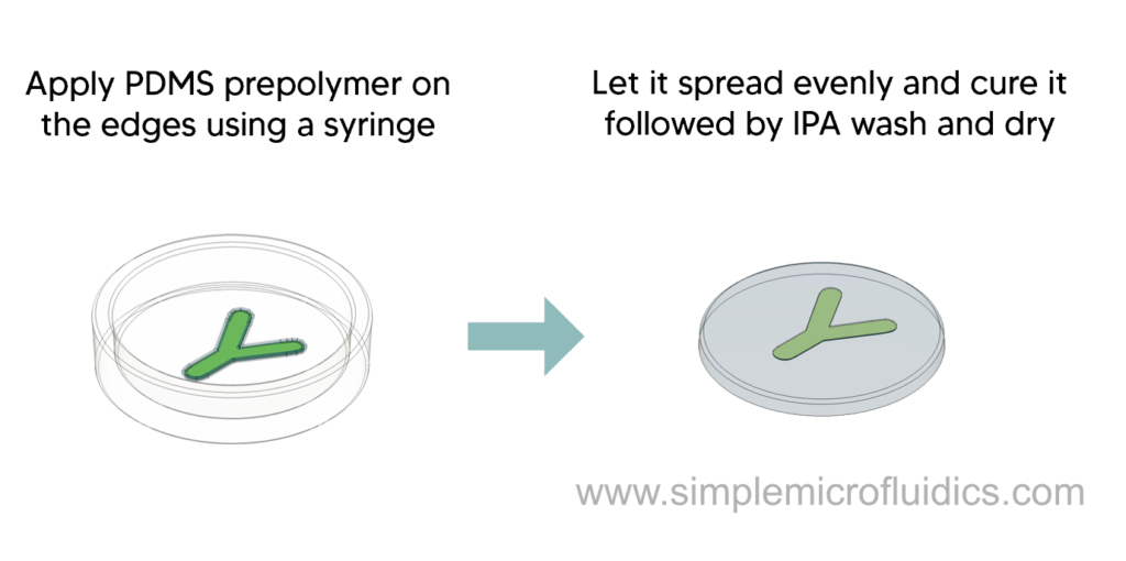
- Take the silicone prepolymer in a syringe and apply it around the coated vinyl template – allow it to flow slowly over the template
- Let it cure at for 24 hours at room temperature and then cut out the PDMS circuit with a scalpel
- Rinse it with IPA to remove excess surfactant and then dry under nitrogen gas followed by adhering to a microscope slide to get a completed circuit


This paper from McMaster University includes a detailed protocol for the above technique – including comparing the different surfactants using an array of modified PDMS chips.
PEGMEM Modification
Overview
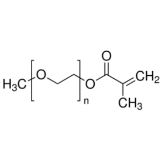
This technique mixes PEGMEM into PDMS before curing to create a stable hydrophilic surface and reduce non specific protein adsorption.
Mix PEGMEM (an amphiphilic copolymer) into the base PDMS prepolymer before curing in an oven. After curing, when the circuit is exposed to an aqueous medium, the copolymer self-organizes on the PDMS/water interface to expose the hydrophilic end of the chain. This creates a hydrophilic surface that can retain its stability for a period of 20 months.
0.5% (w/w) of PEGMEM led to a contact angle just below 95 degrees as well as a 70% decrease in nonspecific protein adsorption.
Technique
- Add 0.25 – 2% (w/w) PEGMEM to the PDMS prepolymer before curing
- Fabricate your PDMS circuit as usual and cure in an oven (high ratios of PEGMEM above 1% require a longer curing time)

This paper provides detailed data of the effects of this technique on biocompatibility, wettability, protein adsorption and the mechanical and optical characteristics of the circuit. It also contains details about the fabrication protocol the authors used to fabricate their PDMS circuits.
PVA Deposition
Overview
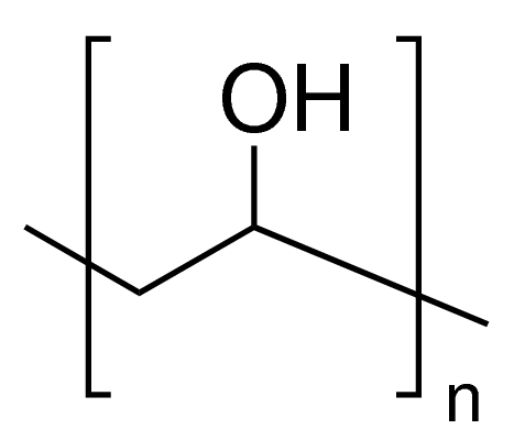
This method is simple, quick and cheap. It uses polyvinyl alcohol (PVA) to decrease the hydrophobicity of PDMS. You can also selectively coat specific channels by passing air through the channels that should remain hydrophobic.
Technique
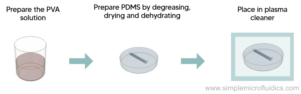
- Add PVA to Milli Q water (1 % wt) and stir at room temperature for 40 minutes
- Gradually raise the temperature to 100°C and stir for another 40 minutes
- Reduce the temperature to 65°C and stir overnight
- Weigh the container and add water to compensate for any loss due to evaporation
- Degrease the PDMS circuit in IPA, blow dry with nitrogen and dehydrate in an oven at 110°C for 40 mins
- Place the circuit in a plasma cleaner at 100 W for 1 min and 20 sccm oxygen flow and 0.65 mbar pressure
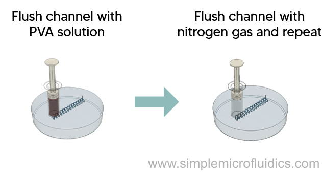
- Flush the channels with PVA solution and let it sit for 10 mins at room temperature
- Pass pressurized nitrogen through the channels and heat it at 110°C for 15 min to remove any residual moisture
- Repeat the coating three times to achieve a sufficient level of surface hydrophilicity and remove all traces of wetting
For selective modification, pass air through the hydrophobic channels at ~200 μL /min using a syringe pump while passing the PVA solution through the channels that require the hydrophilic coating.


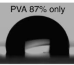
The paper details the PVA deposition technique and and tests it using droplet generation/double emulsion circuits. You will also find details for contact angle measurements in this paper.
LBL Deposition
Overview
This method uses thin composite films of polyanions and polycations that are deposited onto the channel surface. These thin films prevent non specific proteins from binding on the surface.
Technique
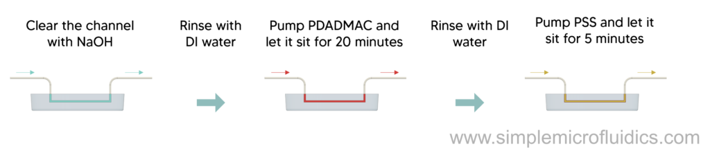
- Condition the PDMS circuit by running 1 M NaOH for 30 mins through the microchannels followed by a water rinse for 3 minutes
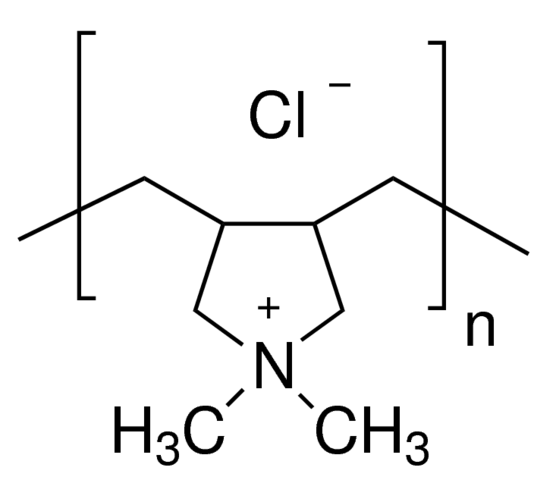
- Then use a vacuum pump to run a buffer solution of 0.02% v/v PDADMAC in PBS in the microchannels and let it stand for 20 minutes to form a PDADMAC layer on the walls of the channel
- Pump out the excess PDADMAC and rinse the channels with doubly distilled water for 5 minutes
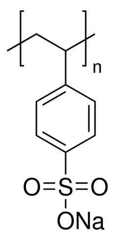
- Repeat the same process with PSS for 5 minutes to form a PSS layer on the PDDA layer via electrostatic interaction followed by a 5 minute water rinse
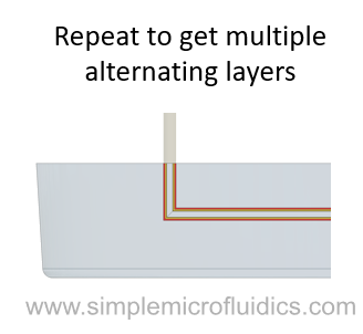
- Repeat this procedure as many times as needed to get desired number of layers

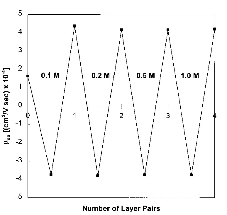
This paper details the modification procedure as well as the effects of the polyelectrolyte layers on the PDMS circuit.
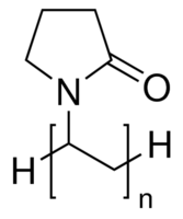
PVP Coating
Overview
This method is used to selectively convert the PDMS surface and make it hydrophilic / oleophobic.
Technique
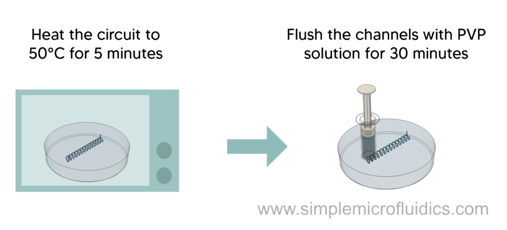
- Prepare the polyvinylpyrrolidone (PVP) solution by mixing 3% to 13% (wt/wt) of PVP powder with DI water
- Heat the PDMS circuit to 50°C in an oven for 5 minutes
- Flush the microchannels with PVP for 30 minutes to obtain the hydrophilic / oleophobic coating
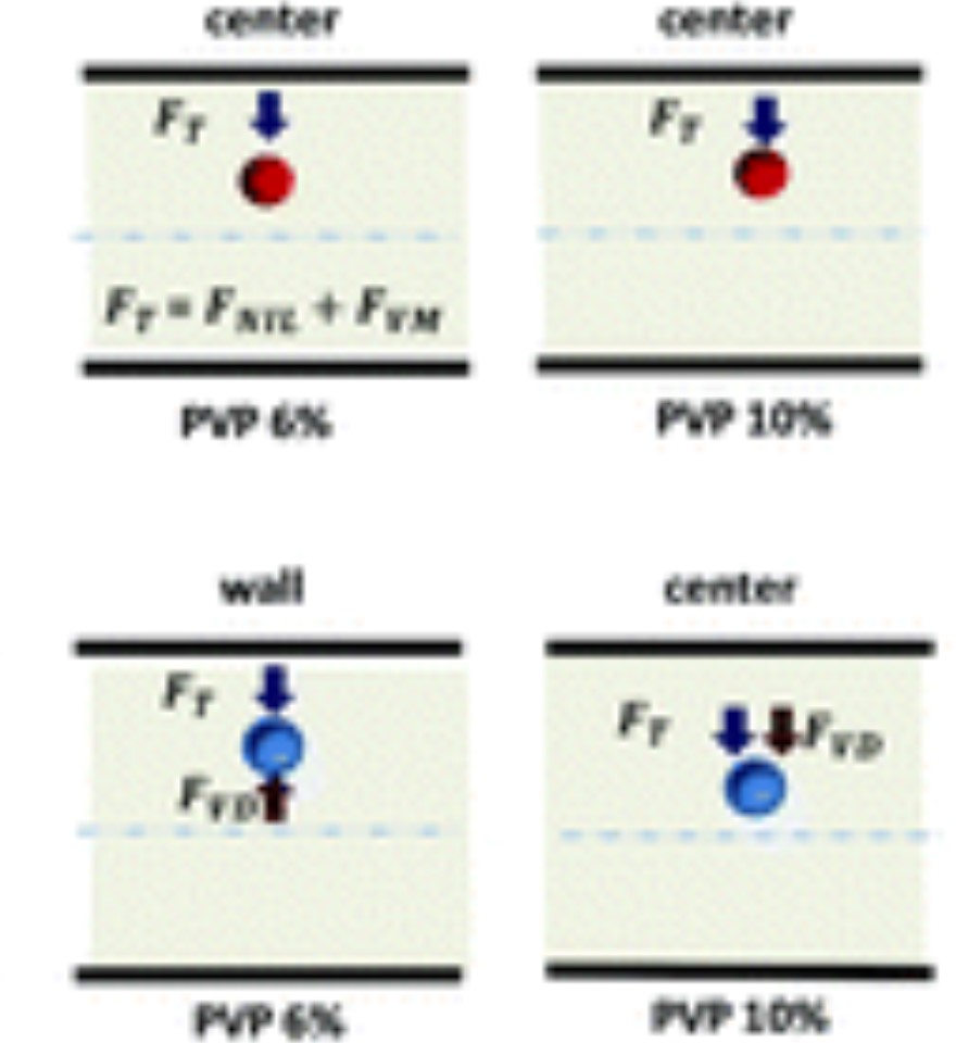
The “device fabrication and experimental setup” section of this paper talks about this surface modification technique. The paper then uses it to generate castor oil droplets in an aqueous phase.
Silanization
Overview
This is a click chemistry based surface modification method that prevents non-specific protein adsorption and enhances separation performance for amino acids and proteins.
Technique
Steps:
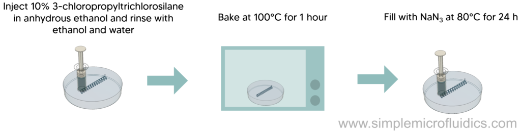
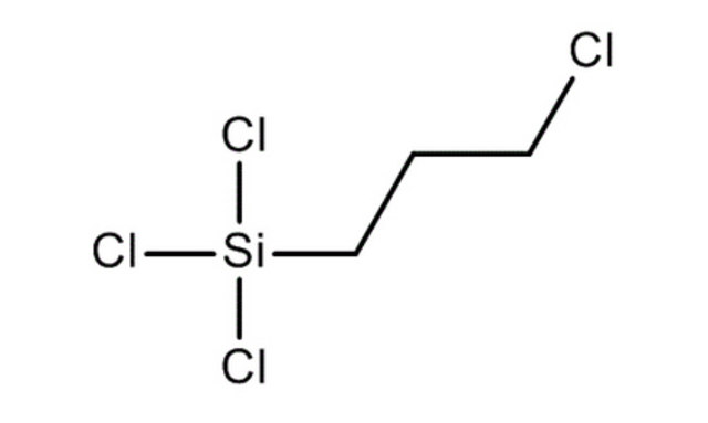
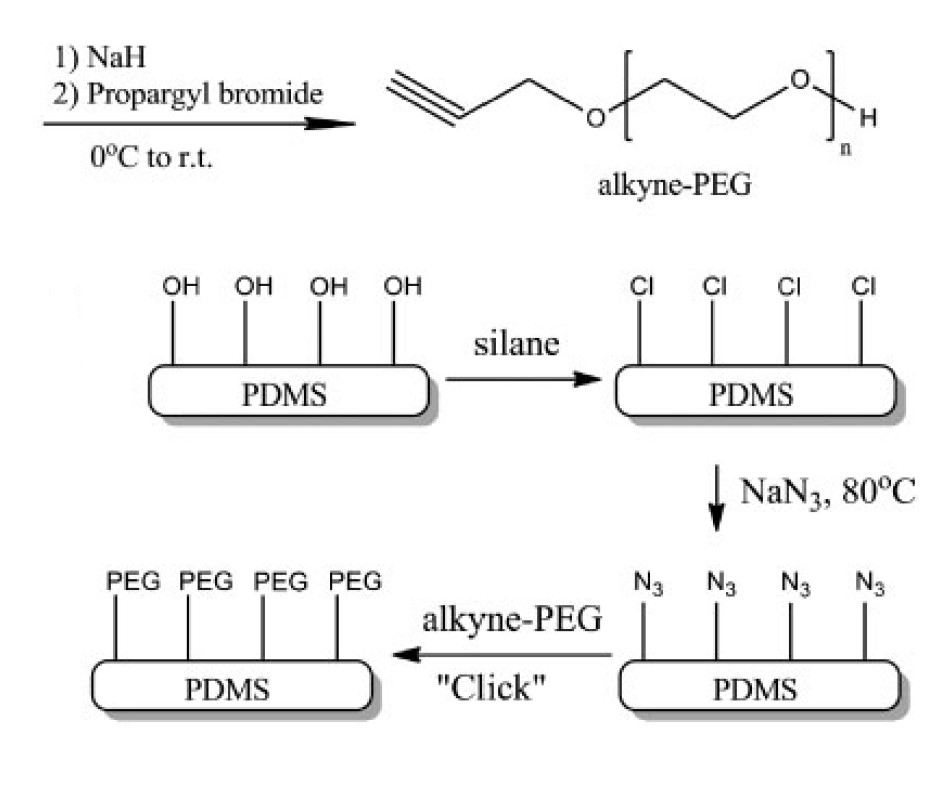
- Inject the PDMS microchannel with 10% 3-chloropropyltrichlorosilane in anhydrous ethanol and let it sit for 2 hours. Then rinse the channel by passing ethanol and water using a syringe.
- Bake the PDMS circuit at 100°C for 1 hour and then fill the microchannels with saturated NaN3 (in 100mM NH4Cl) at 80°C for 24 hours to make azido-PDMS microchannels .
- Rinse the microchannels thoroughly by running water through them with a syringe.
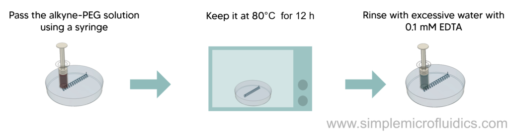
- Pass an aqueous solution containing 100mM alkyne-PEG in the presence of 2mM copper sulfate and 10mM sodium ascorbate through the azido-PDMS microchannels with a syringe for in-situ surface modification.
- Keep it at 80°C for 12 hours
- After cooling down to room temperature, rinse with excessive amounts of water with 0.1mM EDTA to remove the excess copper.
Equipment
Alkyne PEG (Synthesized according to this paper)

This paper details the simple, rapid and versatile method to modify the surface of PDMS circuits.
Chemical Micropatterning
Overview
This method is used to prepare a PDMS elastomer functionalized with atom-transfer radical polymerization (ATRP) initiator. This drives both hydrophilic and hydrophobic molecules to the surface replicating a pattern on a template surface. The researchers managed to get a hydrophilic surface by curing undec-11-enyl hexaethylene glycol monomethyl ether (PEG6) doped PDMS with θadv ≈ 100° and θstat ≈ 90°.
Technique
Steps:
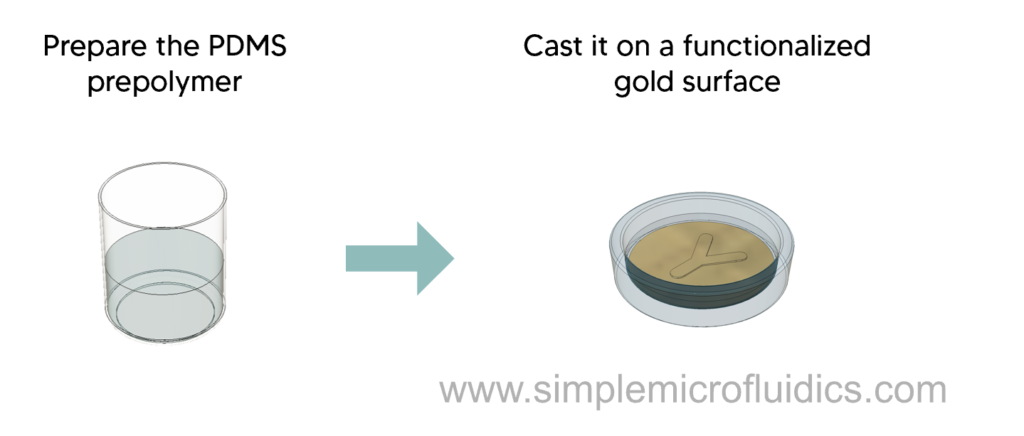
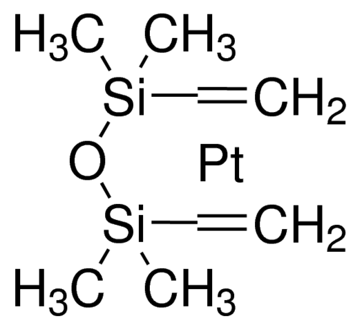
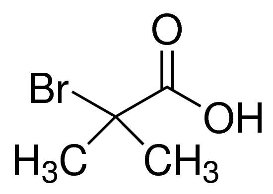
- Mix two parts of the PDMS kit (Sylgard 184, VWR) in a 10:1 ratio by weight to a total mass of 4.0 g, and add 2-bromo-2-methyl propionic acid allyl ester (15 µL, 94.3 mmol) and Pt catalyst (platinum(0)– 1,3-divinyl-1,1,3,3-tetramethyldisiloxane complex) (0.5 µL 0.10 M).
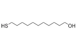
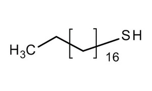
- Cast the mixture against a gold surface functionalized with either an octadecanethiol (ODT) self assembled monolayer (SAM), 11 hydroxy-undecane-1-thiol (HUT) SAM, or mixed patterned SAM of ODT and HUT.
- Leave the PDMS for 24 hours at room temperature, then cure at 70°C, soak in water, and peel off the gold surface.
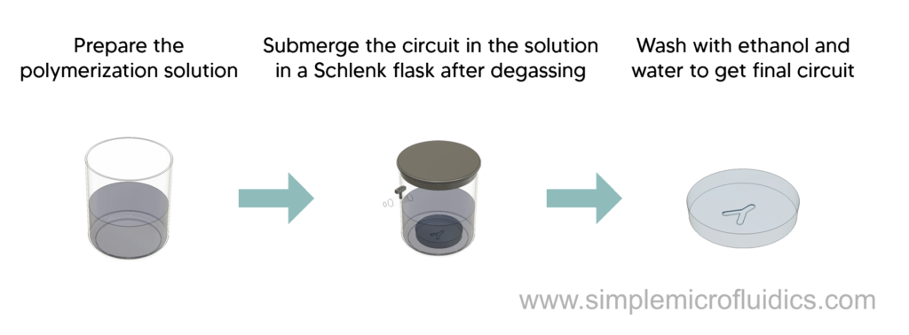
- Dissolve Methoxy-terminated OEGMA (MW 400, 11 g, 23 mmol) in 11 cm³ water at 40 °C and then degass by passing through a stream of dry nitrogen gas while stirring for 15 mins.
- Add 2,2’-Bipyridyl (183 mg, 1.2 mmol), CuCl (46 mg, 469 µmol), and CuBr2 (10 mg, 47 µmol) to this solution. Stir the mixture whilst degassing with dry nitrogen for 15 minutes.
- Seal the initiator functionalized PDMS circuit in a Schlenk tube, degass, and heat to 40°C.
- Transfer enough of the polymerization solution to the Schlenk tube via a syringe to cover the PDMS completely.
- Remove the circuit after 4 hours and wash with water, then ethanol followed by drying under a stream of nitrogen gas.


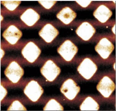
This paper details the surface modification technique as well as uses this technique to create a selectively patterned PDMS surface.
Polymer Brushing (grafting-to approach)
Overview
In this method, polymer groups are used to get desired properties such as chemical and mechanical robustness, and high degree of synthetic flexibility.
In this method, preformed functionalized polymer chains are attached to the surface.
Technique
Steps:
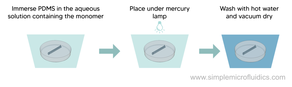
- Immerse the PDMS chip in an aqueous solution containing NaIO4 (0.5 mM), benzyl alcohol (0.5% by weight), and the monomer at the indicated concentrations and ratios. (Source for ratios, Table 1)
- Place the immersed chip under a 200W mercury lamp at a distance of 5 cm for 3 hours. Rotate the specimen to ensure uniform exposure.
- Wash the specimen in distilled water at 80 °C under constant stirring for 24 hours to remove adsorbed monomer and polymer.
Grafting-to technique is described in detail by the paper and it discusses the relation between monomer ratios, contact angle and µeo.
Polymer Brushing (grafting-from approach)
Overview
Technique
In this method, active sites are generated on the surface which on exposure to monomers initiate the growth of polymer chains. This method can generate thicker and denser coatings.
Steps:
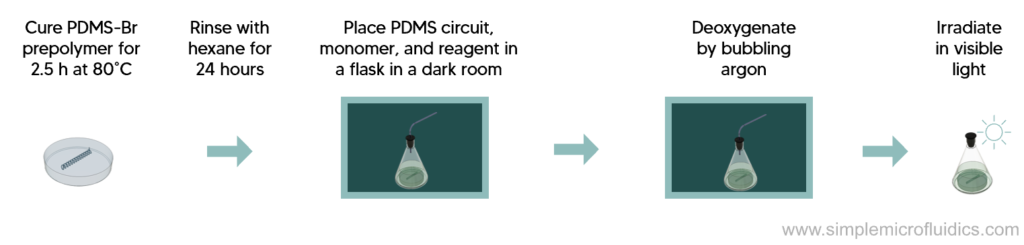
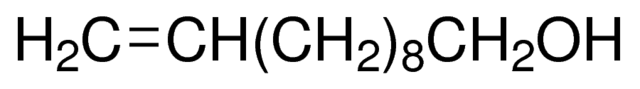
- Prepare the PDMS prepolymer by mixing base : curing agent (Sylgard 184) : undec10-enyl-2-bromo-2-methylpropanoate in a mass ratio of 10/1/0.13.
- Then cure the PDMS at 80°C for 2.5 hours and wash with hexane for 24 hours.
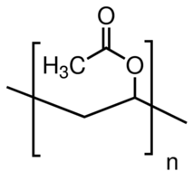
- In a dark room, place Vinyl acetate (VAc ) (1.86 g, 20 mmol), Dimanganesedecacarbonyl (Mn2CO10) (3 mg, 0.0077 mmol), and the PDMS-Br circuit in a flask capped with a rubber septum.
- Deoxygenate the solution by bubbling argon gas for 20 minutes and then irradiate with visible light at room temperature.
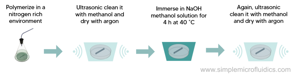
- Polymerize the solution under a nitrogen atmosphere for an appropriate time.
- Take the PVAc-grafted PDMS out of the solution, ultrasonically clean it with methanol and then dry it with argon gas.
- Take the PDMS circuit and immerse in 5% NaOH methanol solution at 40 degree C for 4 hours. Then clean ultrasonically with methanol and dry with argon.


This paper details the grafting from technique and compares different vinyl polymers and their properties such as anti biofouling, cell and bacterial adhesion.
Charged Polymers
Overview
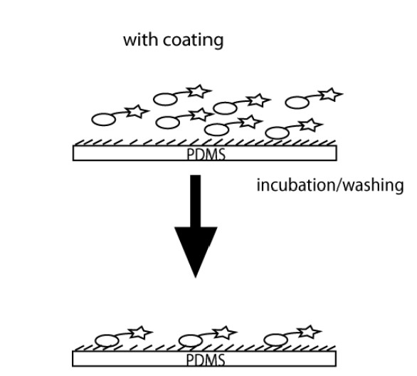
This method can be used to prepare non-biofouling surfaces, allow the channels to resist non-specific protein binding, and provide control over electro-osmotic flow. Although the coating agents can detach from the surface, this method is simple and easy to apply.
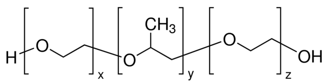
F108 or PLL-PEG can be used as the coating agent as both have long PEG chains which are effective in reducing the adsorption of proteins and controlling electro-osmotic flow. There are two techniques that can be used to apply this coating – static and dynamic.
Dynamic coating is more efficient at reducing electro-osmotic flow. Using an F108 dynamic coating – a 90% reduction in electro-osmotic flow was observed compared to 43% reduction from static coating.
Both methods are equally effective in reducing adsorption of proteins on the surface. Since dynamic coating is a much faster and easier technique, if the coating agent does not interfere with the sample, dynamic coating will likely be your preferred technique.
Static Coating
Technique
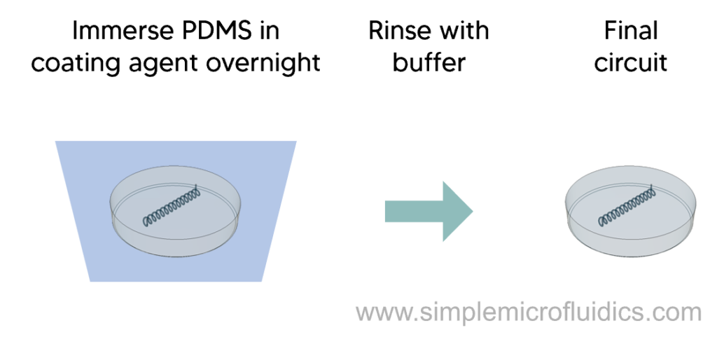
- Prepare the coating agent solution by dissolving the coating agent (F108 or PLL-PEG) in 20mM phosphate buffer (potassium phosphate monobasic and potassium phosphate dibasic anhydrous) at pH 7
- Submerge the PDMS circuit in the coating agent solution overnight
- Remove and rinse with phosphate buffer
This document from Arizona State University compares the different approaches to surface modification and also analyses the long term stability of the coating.
Dynamic Coating
Technique
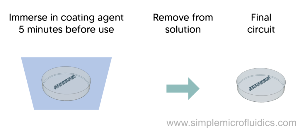
- Prepare the coating agent solution by dissolving the coating agent (F108 or PLL-PEG) in 20mM phosphate buffer (potassium phosphate monobasic and potassium phosphate dibasic anhydrous) at pH 7
- Incubate the assembled PDMS circuit in the coating agent solution 5 minutes before use
- Remove and use as-is without rinsing
This document from Arizona State University compares the different approaches to surface modification and also analyses the long term stability of the coating.
Silicon-Oxide Layer Through UV/Ozone Treatment
Overview
This method can be used to modify the surface of PDMS circuits at room temperature to increase electro-osmotic flow stability, improve wettability, and minimize adsorption of analytes in micro-channels.
The PDMS circuit is exposed to a UV/O environment which converts a ~10µm layer of the surface to silicon-oxide without surface cracking defects.
Technique
Steps:
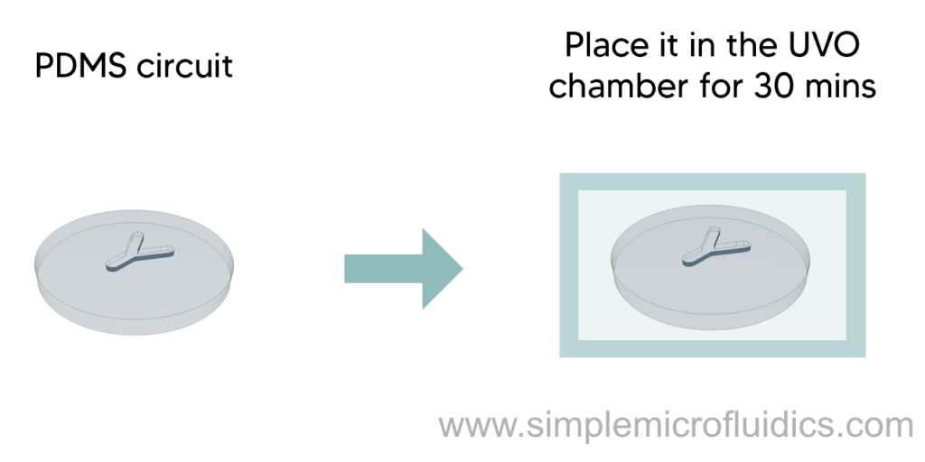
- Both halves of the PDMS circuit are treated in a commercial UVO cleaner. The cleaner generates ozone by the interaction of 185 nm UV light with oxygen present in the air.
- The circuits are exposed for a total of 30 minutes intermittently to prevent the temperature from exceeding 100°C.
- After the treatment, a glass-like layer is formed on the surface that prevents bonding of the two halves.
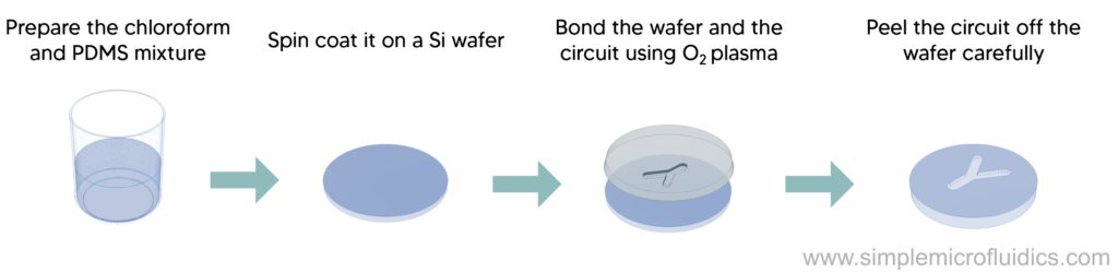
- To overcome this, dissolve a small quantity of PDMS premix in chloroform (0.1 g of PDMS per 10 ml of chloroform), spin-coat on a Si wafer at 3000 rpm, and cure it.
- A thin film of 100 nm thickness will be formed on the surface of the wafer which can be bonded to one of the treated halves by using the oxygen plasma bonding procedure.
- Carefully peel off the PDMS circuit off the wafer. The circuit will pull the untreated thin layer with it on surfaces that came in direct contact with it, whereas the portion of the thin film near the channels will tear at the edges, staying on the Si wafer.
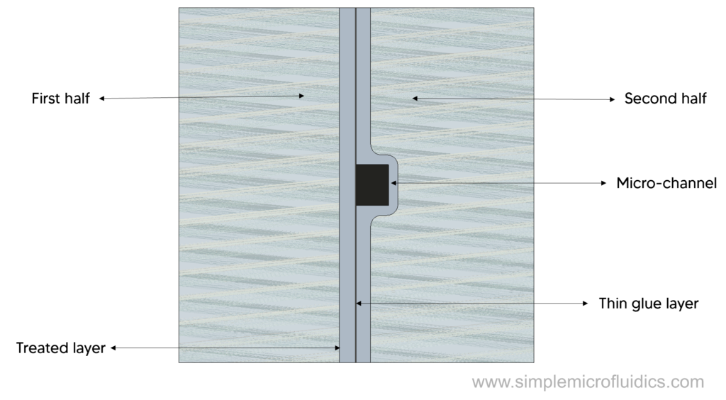
- Thus, this thin glue layer can now be again treated with oxygen plasma to bond it to the other half resulting in a sandwich like cross-section.
The circuit is treated for a limited time to prevent cracking of the oxidized surfaces, presumably due to the stresses between the treated and untreated PDMS layers.
Equipment
This paper demonstrates the UVO oxidization method along with the effects of different exposure time on the properties and also the joining of two treated surfaces.