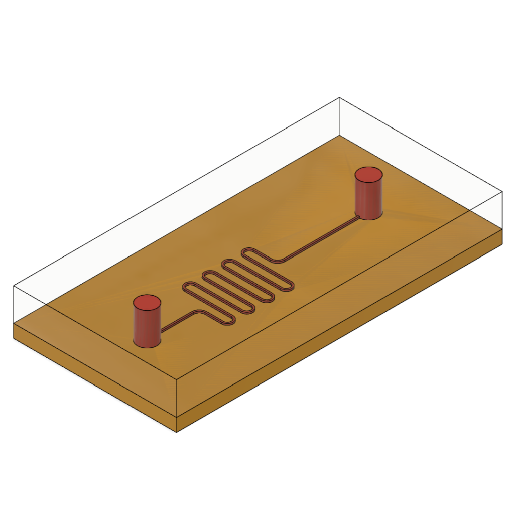
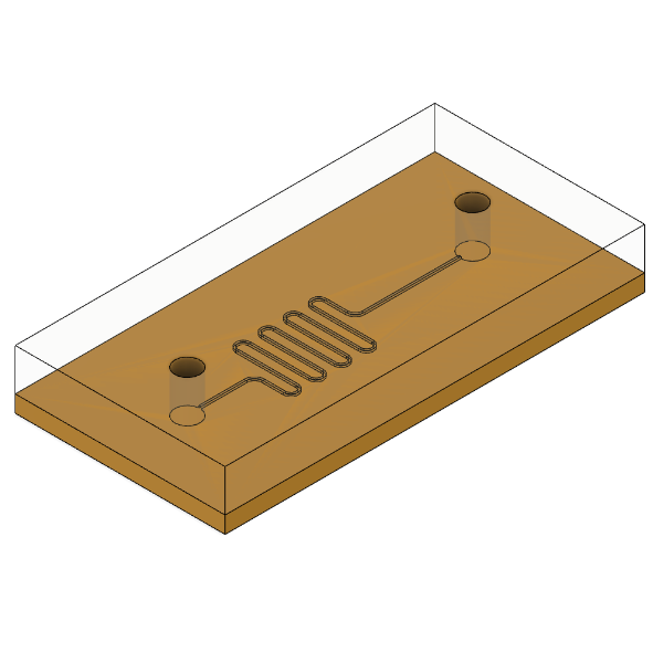
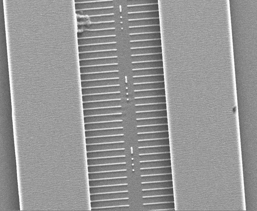
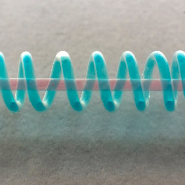
This is a really interesting example of a microfluidic circuit molded in PDMS.
If you want to read more about this research, check out the paper at https://pubs.acs.org/doi/abs/10.1021/ac800492v
PDMS microfluidic molding basics
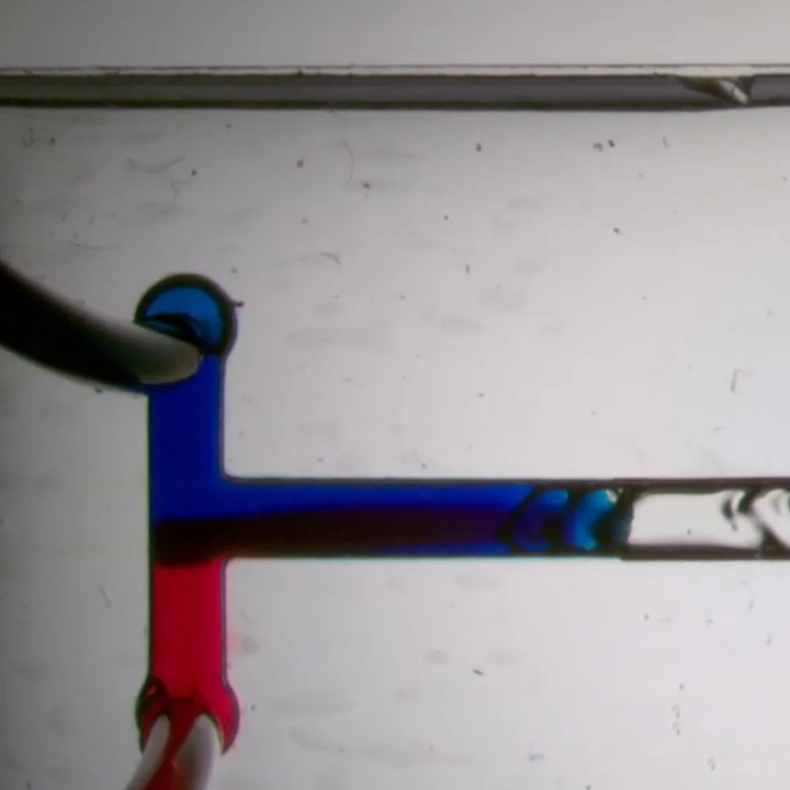
Here’s a video that demonstrates the concept of molding a microfluidic circuit.
First let’s look at a top-level overview of what molding a microfluidic circuit means. Later in this article you will learn a couple of detailed ways of applying this broad principle to making microfluidic circuits for yourself.
Step 1
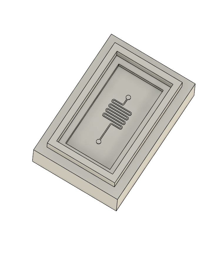
Design the circuit you want to prototype
Step 2
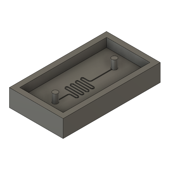
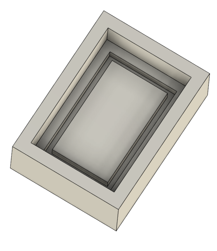
Design and fabricate a mold that you can use to cast the PDMS resin
Step 3
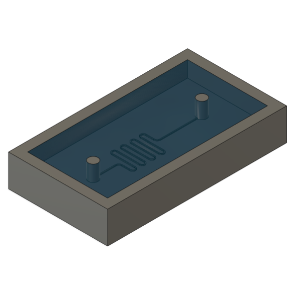
Mix and pour the PDMS into the mold and allow it to cure
Step 4
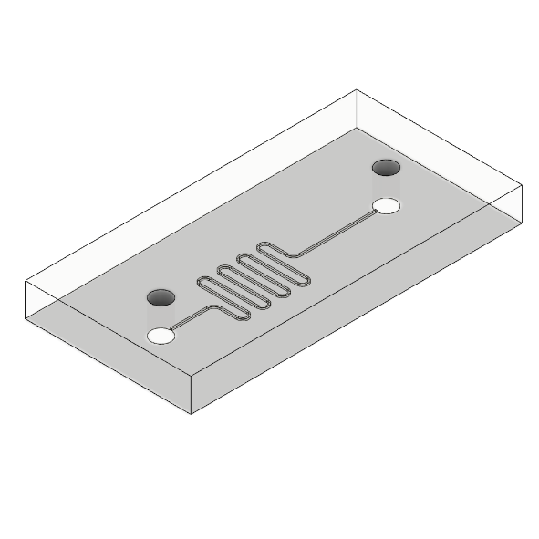
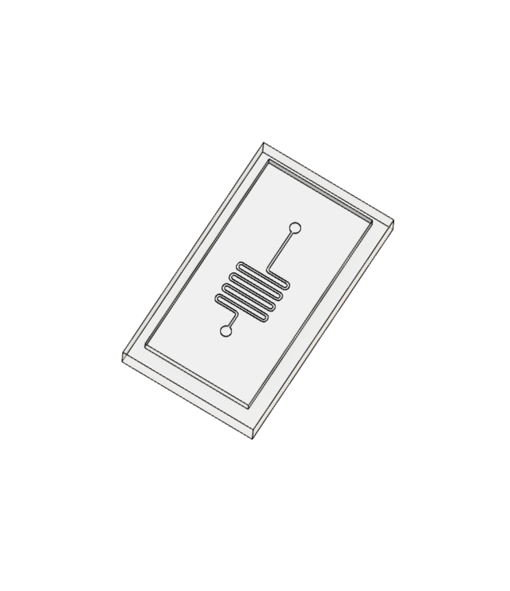
Remove the cured PDMS circuit from the mold
Step 5
Connect the PDMS circuit to a backing layer such as glass or acrylic to form a seal and create the closed microfluidic channels for liquid to flow through
After this you can connect your tubes to the fluid channels and start using the circuit.
Advantages of PDMS molded microfluidic circuits
- Repeatable process – once you dial in your prototyping process you can continue to make circuits without too many modifications to the process
- You can embed electronics such as heating elements into your circuit
- With the right mold design you can create 3D channel geometry
- You can design active components like valves right into the circuit (example)
Disadvantages of PDMS molded microfluidics
- The main disadvantage is that molding PDMS circuits is a very manual process and will require you to spend time making each individual circuit
- You will also want access to equipment (such as 3D printers and ovens) if you’d like to make these quicker and with a fine channel resolution
What is PDMS?
PDMS is a 2 part resin. You mix the base with the curing agent, pour it into your mold, and allow it to cure and take on the designed shape.
Application note for PDMS: A 10:1 base:curing agent ratio by weight is a good starting point for PDMS (Sylgard 184) – add less curing agent for a softer circuit and more for a harder circuit.
Why PDMS?
- Very flexible – which makes it easy to seal and more durable
- Optically transparent – also allows you to add accessories like cameras onto the circuit to help you analyze the flow
- Reasonably biocompatible
- Takes on fine details very well
- Can be bonded with glass
- PDMS flexibility can be used to integrate active components such as valves right into the circuit (example)
- Tuneable gas permeablity – the gas permeability of PDMS can be tuned by varying the thickness and base:curing agent ratio during mixing
- Well studied for microfluidic applications – this means you have access to a variety of research papers that will show you techniques that allow you to modify the surface properties and bulk properties of PDMS
How to make PDMS microfluidics
- 3D Printed Mold to Cast a PDMS Microfluidic Circuit
- Puffy Paint Mold to Cast a PDMS Circuit
- Duplicating an Existing Microfluidic Circuit By Casting PDMS
- Cutting ABS Sheets to Mold PDMS Circuits
- Dissolving 3D Printed ABS to Cast a PDMS Circuit
3D Printed Mold to Cast a PDMS Microfluidic Circuit
Overview
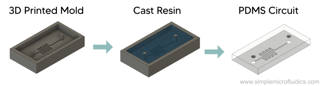
This is one of the fundamental techniques of prototyping microfluidics. Here you use a 3D printed mold and cast PDMS into it to create the microfluidic channels. This is then bonded to a glass slide and sealed to form the complete microfluidic circuit. This is an accurate and repeatable technique but the drawback is it is not easily scaleable as you need to put in the time to make every single circuit. It is a great technique for lab-scale prototyping and if you have access to all the equipment, you can design and prototype your circuits within the same day.
Equipment


Weighing scale
You will need this to mix the PDMS base and curing agent to the correct ratio. An accuracy of 0.1 gram is good enough. Unless you make very large circuits, you can probably make do with a ~500 gram scale. The density of PDMS is ~1.03 grams/ml so to make a large 10cm x 10cm x 1cm circuit you will need to make around 105gms of PDMS.

Vacuum chamber
When the PDMS is mixed it will often form bubbles. Using a vacuum chamber to degass the PDMS will remove these bubbles from the resin and allow you to mold your channels more accurately and provide you with a more optically transparent circuit.

Oven (optional)
You can use this to speed up curing of the resin so that it cures in 15 to 45 minutes. If you don’t have access to an oven then you can leave the resin to cure for longer (24-48 hours). In a pinch you can also experiment with using a hotplate to accelerate curing.

Biopsy punch (optional)
You can use a biopsy punch to make a hole in the PDMS circuit to insert your tubes and connectors. It’s not hard to find another tool to use instead (syringes work great), but this is nice to have if you’ll be working on these circuits often.

Glass microscope slides
Glass slides will form the backing layer of your circuit. Once you’ve molded the channels into PDMS you can bond them to the glass slide and form a sealed closed channel microfluidic circuit.
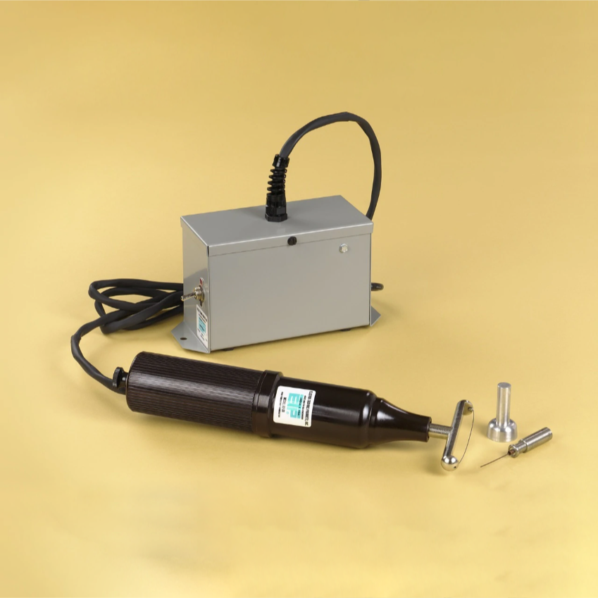
Corona Oxidizer
You will need a corona oxidizer to oxidize both the glass slide and the PDMS surfaces and allow them to chemically bond and form a good seal.

Hot plate
After joining the glass slide and PDMS circuit you should use a hotplate to complete the bonding process. You could also experiment with using an oven instead.
This video from Hashimoto Lab at the Singapore University of Technology and Design is a detailed and easy to follow guide on how to make microfluidics devices by casting PDMS into a 3D printed mold.
Metal Micromilling to Form a PMMA Master
Overview
In micromachining, a CNC machine is used to remove material from a substrate. The substrate for a metal master can be made of brass, aluminum, or copper. The micromachines are capable of achieving positional and repetition accuracy of ±1 µm with tooling bits ranging from 50 to 500 µm.
Technique
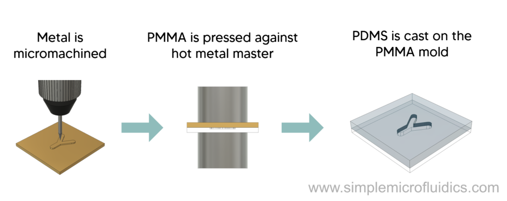
Steps:
- The substrate is CNC-ed to create a negative metal master.
- The metal master and the PMMA disk are placed in a hydraulic press with an integrated vacuum chamber.
- The metal master is pressed on to the PMMA disk for 5 minutes at 155°C.
- The PMMA mold is then cleaned and sprayed with mold release.
- PDMS is cast into this mold to make microfluidic chips.
Equipment
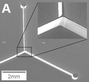
This paper details a cost-efficient method of microfluidic circuit fabrication through micromilling a metal mold and using that to create a PMMA master over which PDMS is cast.
Puffy Paint Mold to Cast a PDMS Circuit
Overview
This is an ingenious concept from Wisconsin Materials Research Science and Engineering Center.
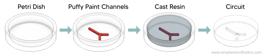
A mold is created by using puffy paint to draw the circuit onto a petri dish. This is then cast with PDMS to create microfluidic channels. This PDMS component is then sandwiched between two sheets of acrylic to complete the circuit.
Equipment

Puffy paint. You will use puffy paint to “draw” the channels onto the petri dish.

Petri dish. The petri dish forms the backing for the puffy paint and is a very convenient container to mold your PDMS circuit in.
Vacuum chamber
When the PDMS is mixed it will often form bubbles. Using a vacuum chamber to degass the PDMS will remove these bubbles from the resin and allow you to mold your channels more accurately and provide you with a more optically transparent circuit.

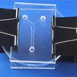
Acrylic sheet. You will need to cut this and bond it to the PDMS so that it forms a seal with the molded channels and creates a microfluidic circuit.

A way to cut the acrylic sheet. You could use a Dremel or a laser cutter. Because this component is meant to seal with the PDMS, we don’t recommend 3D printing it as a 3D printed part is harder to seal due to surface imperfections.

Binder clips. Once your circuit is molded you will use binder clips to sandwich the PDMS circuit between two acrylic sheets. This will apply pressure onto the PDMS <> acrylic interface and form a better seal.
Check out this video from Wisconsin Materials Research Science and Engineering Center to learn a quick, easy, and cheap way to prototype low fidelity microfluidic circuits through PDMS molding.
Duplicating an Existing Microfluidic Circuit By Casting PDMS
(aka moldception)
Overview
The main aim of this technique is to duplicate a microfluidic circuit that you already have. It’s an extremely capable technique and can replicate features in the 5µm range. This is how it’s done:
You use an existing microfluidic circuit to make a mold. You then cast PDMS into that mold and create a PDMS copy of that circuit.
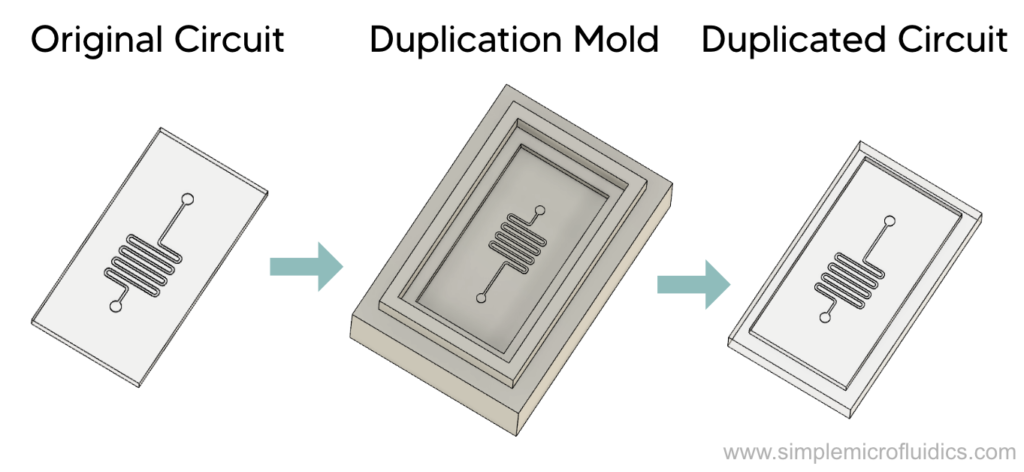
Now let’s talk about how to make a mold using an existing circuit.
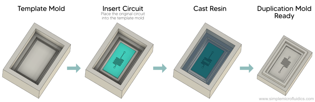
First, place the circuit on a flat surface in a container (called the template mold) and cast resin into it. Once the resin cures, it can be used as a duplication mold to reproduce the circuit you started out with. Just cast PDMS into the duplication mold to make a copy of your original circuit.
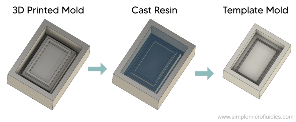
As an aside: the way to make a template mold is also by casting. You can use scrap material lying around to make a mold for your template mold. The dimensions aren’t very critical. Alternatively you can 3D print a mold using this file we’ve prepared and cast resin into it to make your template mold. You will really only need 1 template mold but it’s always a good idea to make backups in case your first one gets damaged or if you want to duplicate multiple circuits in parallel.
Materials
The materials used to make the molds are important because you want a duplication mold that’s made of epoxy so that you can cast PDMS into it. Here’s a material reference chart to make it easier.
3D Printed Mold
Plastic*
Template Mold
PDMS
Duplication Mold
Epoxy
Circuit
PDMS
There are many modifications that could be made to this technique so feel free to contact us if you need help modifying this to suit your lab.
Equipment
Template mold
You need this to make your duplication mold. Read through the overview to understand how to make this part. You can 3D print this file and cast resin into it to make a template mold.

Epoxy
This will be used to make the duplication mold
Vacuum chamber
Bubbles are formed when 2 part resins are mixed. Using a vacuum chamber to degass the resin will remove these bubbles and increase dimensional accuracy and optical transparency.

Weighing scale
You will need this to mix the your casting resins to the correct ratio. An accuracy of 0.1 gram is good enough.
Because you are also making a template mold, it’s better to go with a weighing scale that can measure up to 1kg just to be safe. An accuracy of 0.1grams should be good enough.
Oven (optional)
You can use this to speed up curing of PDMS and epoxy so that it cures in 15 to 45 minutes. If you don’t have access to an oven then you can leave the resin to cure for longer (24-48 hours). In a pinch you can also experiment with using a hotplate to accelerate curing.
This video from Black Box Labs shows you how to duplicate a microfluidic circuit you already have. It is quite capable and can duplicate features down to the 5µm scale.
Note: After you use this technique to make your circuit you need to bond it to a glass slide. You can learn how to do that using a corona oxidizer and a hotplate by reading through this technique. It links to a video by Hashimoto Lab at the Singapore University of Technology and Design and the bonding demonstration starts at 9 mins 15s.
Cutting ABS Sheets to Mold PDMS Circuits
Overview
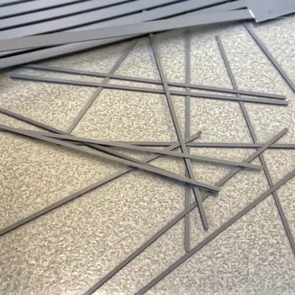
Cut the microfluidic channel geometry out of a sheet of ABS 0.20mm to 0.50mm thick.
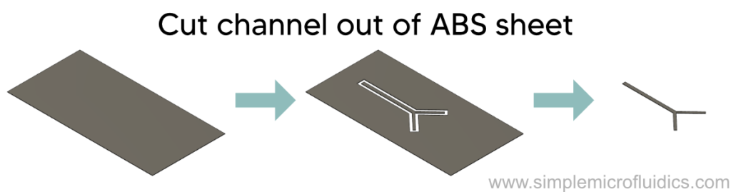
Place the channel geometry in a petri dish and cast PDMS into the petri dish.
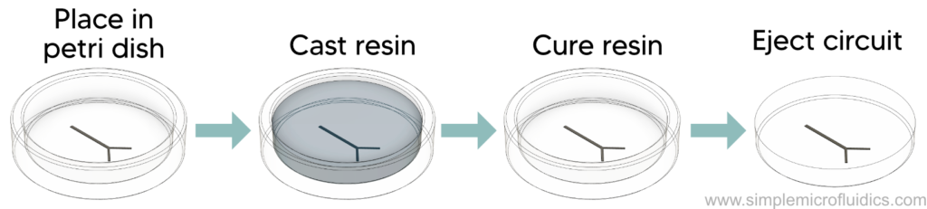
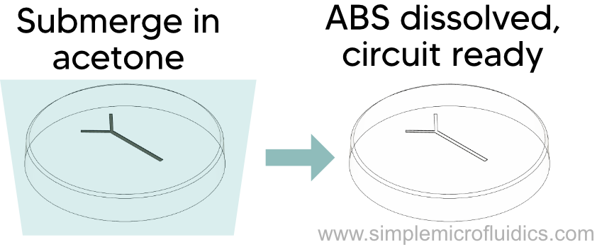
Place the circuit from the previous step in an acetone bath overnight to dissolve the ABS.
Equipment

Plastic Sheet
You will use this to create the channel geometry and place it into the petri dish to create the mold
Note: Although ABS is the recommended material for this technique, you might have trouble finding ABS in low thicknesses. In this case you can experiment with PVC instead as PVC is also soluble in acetone.

Scalpel (or laser cutter, or cutting plotter)
You need a way to cut the channel geometry out of your ABS sheet
Note: If you use PVC plastic sheets, don’t use a laser cutter as it produces toxic fumes
Petri dish.
The petri dish forms the backing for the ABS channel geometry and is a very convenient container to mold your PDMS circuit in.

Acetone
After casting the PDMS in the petri dish, you will submerge the cured circuit in acetone to dissolve the ABS
Biopsy punch (optional)
You can use a biopsy punch to make a hole in the PDMS circuit to insert your tubes and connectors. It’s not hard to find another tool to use instead (syringes work great), but this is nice to have if you’ll be working on these circuits often.
In this video Dr Vittorio Saggiomo shares his expertise and shows you how to create PDMS microfluidic circuits with a simple and cheap setup. He will demonstrate two techniques in this video, one of which is the technique discussed here.
Dissolving 3D Printed ABS to Cast a PDMS Circuit
aka ESCARGOT (Embedded SCAffold RemovinG Open Technology)
Overview
Credit to Dr. Vittorio Saggiomo and Dr. Aldrik Velders for coming up with this technique.
In this technique, you will first 3D print the required channel geometry in ABS. You then cast PDMS into a petri dish and suspend the 3D printed part in the uncured resin.
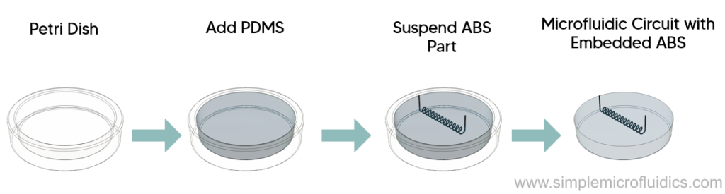
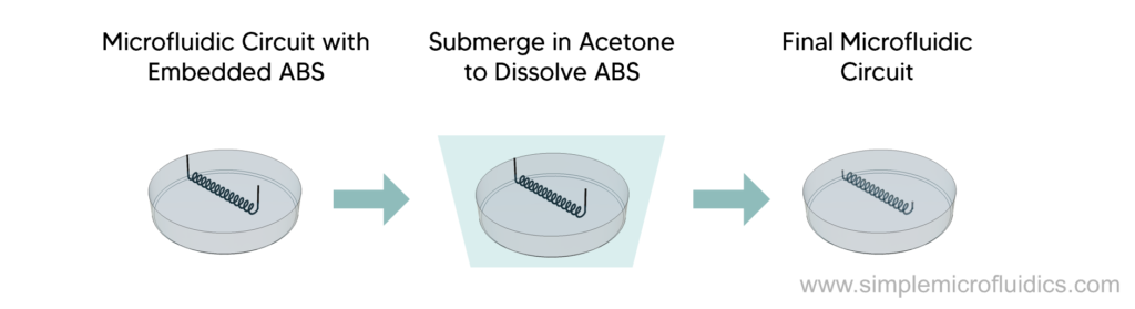
Once the resin cures, you can submerge it in acetone overnight to dissolve the ABS, leaving you with the final microfluidic circuit.
This technique is great for microfluidic circuits with 3D channel geometry or circuits with embedded electronics like heating elements to heat up the fluid in the channels.
Equipment

ABS Filament
This will be used as the scaffold to form the channels in the microfluidic circuit. After embedding it in PDMS, you will use acetone to dissolve it away and leave you with just the microfluidic circuit. Manufacturers will sometimes change their material composition so make sure you test the material before ordering a large quantity. In general, cheaper ABS will have less additives and will dissolve more easily.

Acetone
This will be used to dissolve the ABS

3D Printer (optional)
If you don’t have access to a 3D printer, you could use a service like Hubs. Alternatively you can watch the video linked below which also demonstrates other ways to create your channel shapes such as by using a soldering iron.
Petri dish.
The petri dish will be used as a container to cast the PDMS in. After you have cast the PDMS, you can suspend the ABS scaffold in it and wait for the resin to cure.
Vacuum chamber (optional)
When the PDMS is mixed it will often form bubbles. Using a vacuum chamber to degass the PDMS will remove these bubbles from the resin and allow you to mold your channels more accurately and provide you with a more optically transparent circuit.
Biopsy punch (optional)
You can use a biopsy punch to make a hole in the PDMS circuit to insert your tubes and connectors. It’s not hard to find another tool to use instead (syringes work great), but this is nice to have if you’ll be working on these circuits often.
This video by Dr Vittorio Saggiomo demonstrates different ways to form the ABS scaffold. They also use their experience to demonstrate useful tips and tricks for when you try this technique in your lab.