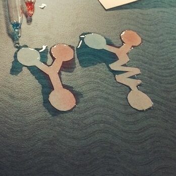
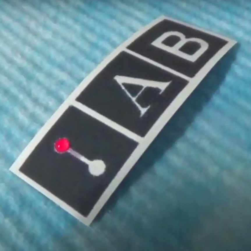
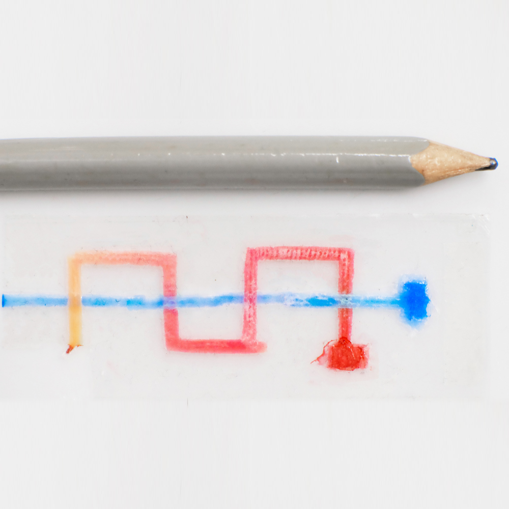
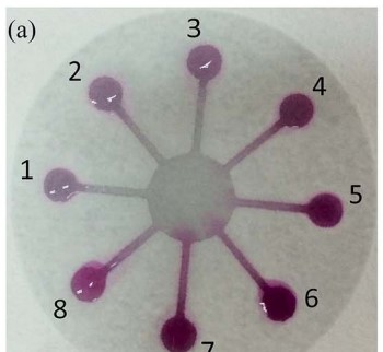
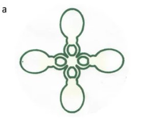
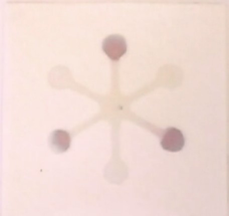
Here is an example of a paper microfluidic device:
What is a paper microfluidic device?
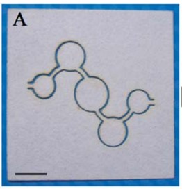
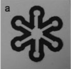
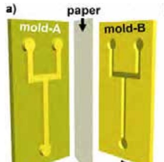
The premise is simple: when a liquid is placed onto paper, the liquid slowly spreads throughout the paper as a result of capillary action. To guide fluid along channels we can use a substance like wax to block the fluid from moving out of the channels. This is the technique used in the video above: the black region is wax that has been impregnated into the paper. Another way of restricting fluid to the channels is to cut paper into the shape of the channels like shown below.
Advantages of paper microfluidics
- Low cost
- Can be easy to prototype
- Doesn’t require pumps as liquid moves because of capillary action
- Reagents can be embedded into the paper
- Fluid flow on a paper is easy to predict
- Paper can be folded to create multi-layer designs
How to make paper microfluidics
Laser Cutting
Overview
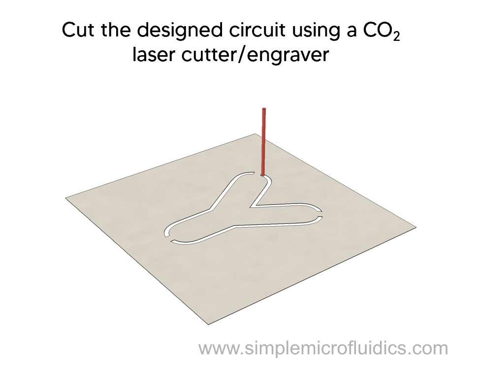
This method uses a CO2 laser engraver/cutter to remove material from the paper substrate. This creates an air gap between the channel and the surrounding paper without the use of any chemicals or processing. This is a one step process and very rapid, 7-20 seconds for a 4×4 cm paper depending on the complexity of the circuit. Each device is fabricated separately and is ready for use as soon as the cutting process is finished. It is highly accessible as even the low cost CO2 engravers can cut paper.
Technique
Technique
- Design the pattern for the hollow microchannel as black lines on a white background in a software of choice.
- Place a sheet of paper flat onto the bed of the CO2 laser cutter/engraver.
- Then set the laser with a spot size of 0.3 mm to cut the paper according to the designed pattern at a current of 5 mA, cutting rate of 20 mm/s, laser wavelength of 10.64 mm and power of 40 W.
This paper presents a one step method to pattern and manufacture paper microfluidic devices.
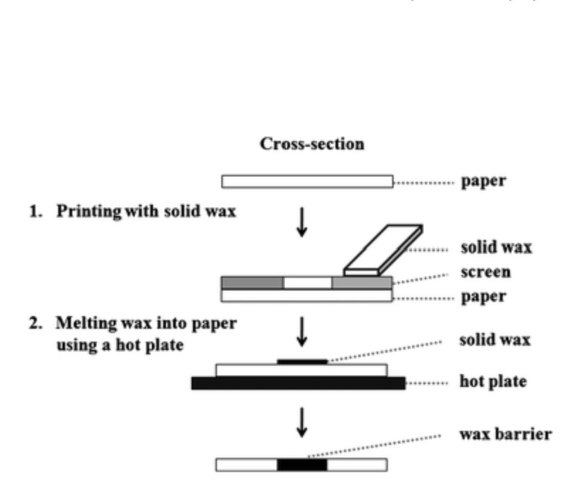
Wax Printing
Overview
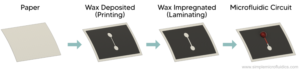
Wax printing microfluidics uses a printer to deposit a layer of wax onto paper. This wax is then impregnated into the paper by laminating the printed paper between two sheets of plastic that act as a protective barrier for the wax. This is a good method for rapid prototyping of microfluidic circuits at low to medium resolution. As a rough estimate, you would want to make sure your solid wax lines are 300μm wide to ensure that they form a barrier and prevent the fluid from flowing across. You can also expect to achieve channel widths of about 500μm.[Source]
Equipment
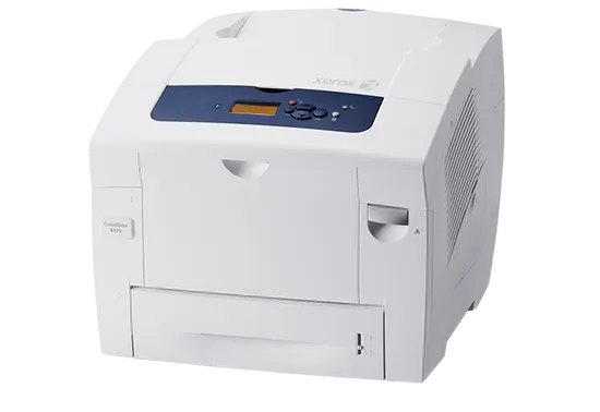
Wax printer such as the Xerox Color Qube. Unfortunately these seem to only be available on the used market at the moment.
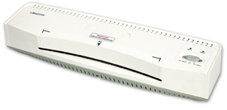
Laminator such as LM4231H
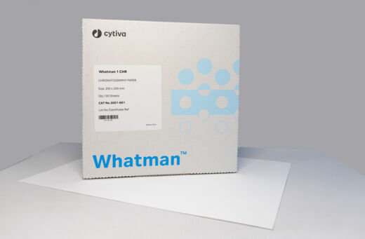
Chromatography Paper such as Whatman Grade 1 Chromatography Papers. Alternatively you could also use a filter paper such as Grade 4 Filter paper.
You’ll need to select your paper based on the printer you plan on using. Page 6 of this paper contains useful information to help you make your choice.
This video from Hashimoto Lab at the Singapore University of Technology and Design is a very concise but informative walkthrough on how to make microfluidics devices by wax printing.
Wax Stamping
Overview
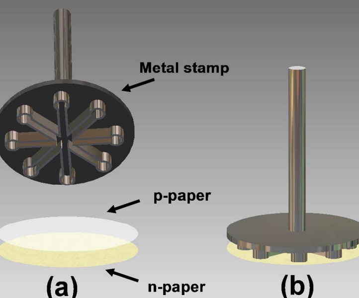
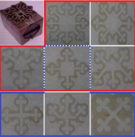
This technique uses a machined metal stamp to transfer wax from one paper to another. You can try to use a company like Protolabs or Xometry to fabricate the stamp after you design it using CAD software.
Technique
Steps
- Fabricate a stainless steel metal stamp
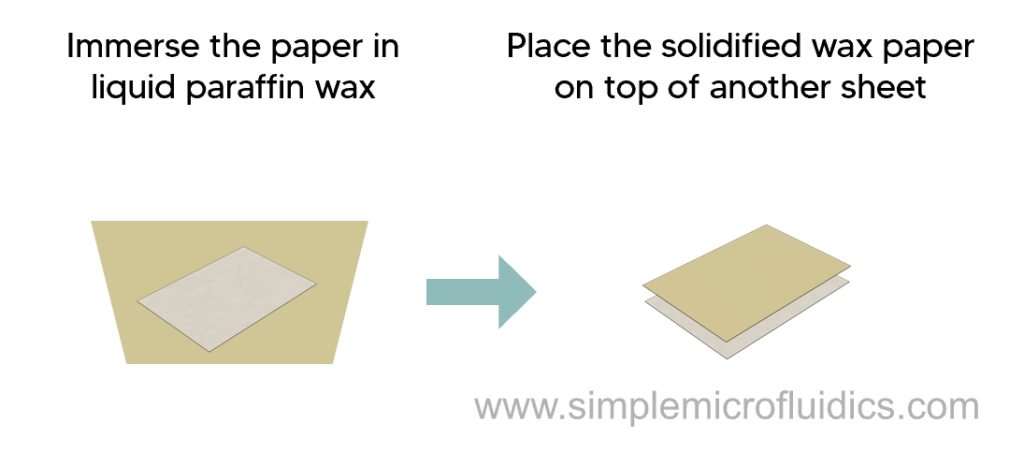
- Immerse a filter paper in liquid paraffin wax at 90°C for 60 seconds.
- Remove the paper from the wax and allow it to solidify at room temperature.
- Place the wax paper on top of a normal filter paper.
- Pre-heat the metal stamp on a hot plate at 150°C for 2 minutes.
- Place the heated stamp on the wax paper and apply slight pressure for 2 seconds to transfer the microfluidic pattern.
The hot stamp selectively melts the paraffin wax which gets absorbed by the paper below to form hydrophobic barriers.
A single stamp can be used to fabricate a lot of devices before needing a replacement. The researchers fabricated more than 5000 devices with the same stamp.
This paper presents a technique to manufacture paper microfluidics by using a metal stamp.
Wax Tracing
Overview
In this technique, a printed template is traced with a wax pen to create the microfluidic circuit.
Technique
Steps:
- Design the pattern using your choice of software.
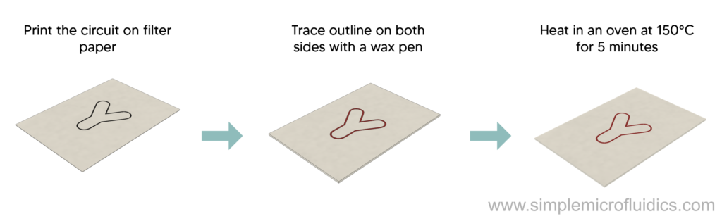
- Print it on a filter paper using an inkjet printer with normal ink.
- Trace the printed pattern on both sides of the paper using a wax pen.
- Place the paper in an oven at 150°C for about 5 minutes
- This will melt the wax and it will penetrate the paper to form a hydrophobic wax wall.
There will be some lateral movement of wax as well due to diffusion of wax and absorbability of paper. This means the final channel width will be a bit smaller than designed.
This is a simple and low cost technique that can be used to rapidly generate flexible and portable paper microfluidic devices.
Movable Type Wax Printing
Overview
This technique uses a set of laser cut movable iron components to create a pattern on a magnetic surface. A variety of patterns can be created by just re-configuring the placement of the iron components.
Technique
Steps:
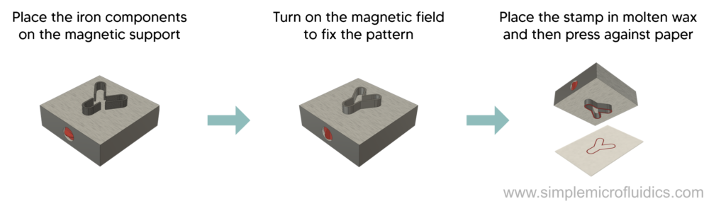
- Cut out the required iron pieces measuring 2 mm thick and 5 mm high using a laser cutter.
- Place the pieces on the iron plate with the magnetic field turned off.
- Adjust the pieces to form the desired pattern and turn the magnetic field on.
- Place the apparatus, pattern side down, in molten wax that is being heated on a hot plate at 60°C. Make sure that the depth of wax is lower than the height of the component i.e. 5 mm.
- Take out the heated patterned iron components that have been coated with a layer of molten wax and place on a filter paper to stamp the wax.
- Let the wax dry and circuit is ready to use.
This paper details a technique that uses moveable iron blocks to create a stamp on a magnetic support block.
Paper-Tape Microfluidics
Overview
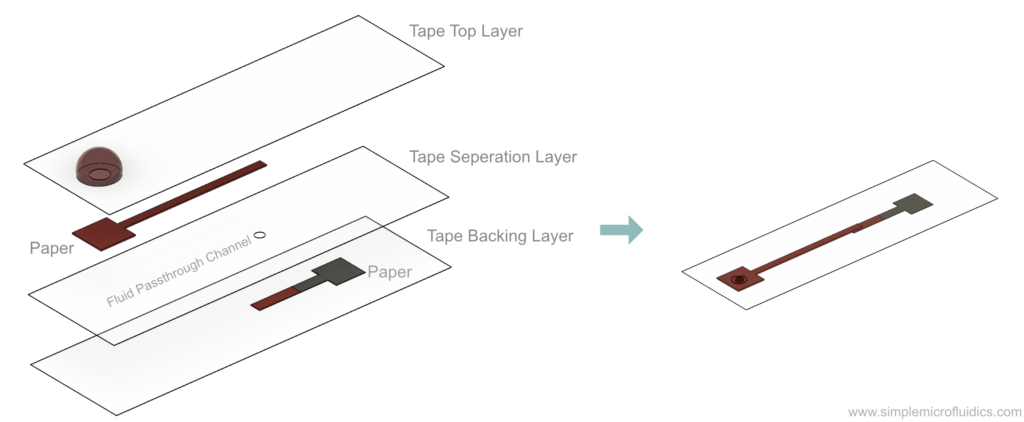
Paper-tape microfluidics works by sticking cut-outs of paper microfluidic channels onto tape. By stacking multiple layers together, you can also make multi-layer circuits. While this method is quite time consuming, it is also extremely low-cost and has a low barrier to entry to getting started. You might be able to find a way to speed things up if you can get access to a laser cutter or a cutting plotter.
Equipment
Alternatively you could also try chromatography Paper such as Whatman Grade 1 Chromatography Papers or Grade 4 Filter paper.
In this article Dr Tempest van Schaik explains how to make a paper-tape microfluidic prototype. She also explores other simple, low-cost, and ingenious ways of mocking up microfluidic circuits.
Stamp Printing Indelible Ink
Overview
This technique uses permanent ink to stamp the circuit design on filter paper.
Technique
Steps:
- Prepare the black Lumocolor ink by reducing it with a solvent mixture made of a 1 : 1 v/v ethanol and propanol in a 10 : 1 ink-solvent mixture.
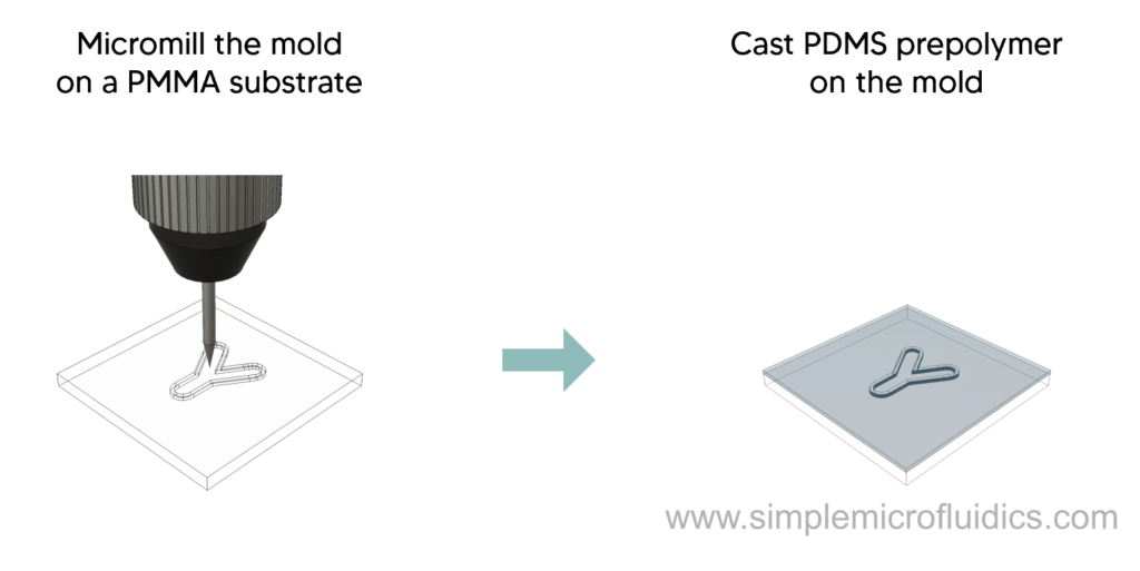
- PDMS is mixed in a 10 : 3 w/w monomer-curing agent ratio
- Then, pour the PDMS on a micromilled poly methyl methacrylate (PMMA) substrate and cure at 60°C for 8 hours.
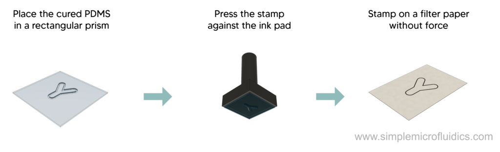
- Remove the PDMS negative mold and attach it to a rectangular prism made of aluminum and a layer of black ceramic material with a total weight of ~440 grams.
- Pour the ink on a stone ink pad and gently push the PDMS stamp against it 3 times and then expose it to air for 5 seconds. This removes any air bubbles trapped on the stamping surface.
- Stamp the ink on a filter paper for 3 seconds without any force.


In this paper, researchers used the hydrophobic property of permanent ink to stamp a microfluidic circuit using a PDMS stamp.
Stamp Printing PDMS
Overview
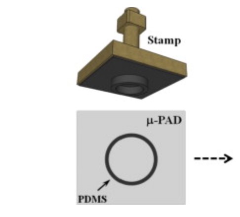
This method uses custom made stamps to deposit PDMS as a hydrophobic barrier for paper microfluidics. The main advantage over standard wax based method is that PDMS is more compatible with organic solvents such as alcohols, amides and sulfoxides.
These stamps can be used for a long period of time without any significant deterioration.
Technique
Steps:
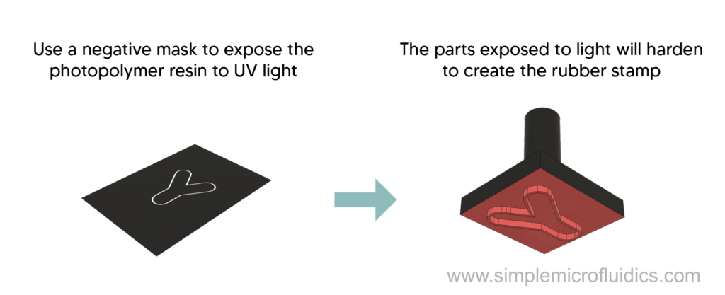
- Print the negative mask of the circuit design on a transparency sheet using a laser printer, i.e. the hydrophobic walls should be left transparent and rest black.
- To make the stamp, expose liquid photopolymer polyurethane to UV light through the printed negative mask.
- The areas exposes to the UV light will harden and the rest of the polymer can be washed away.
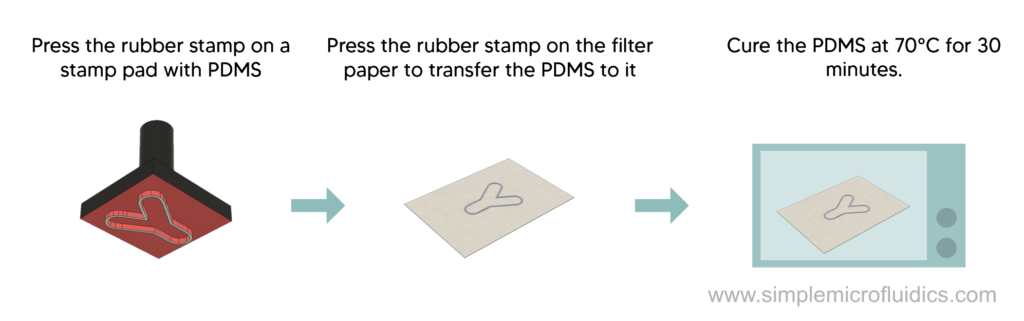
- Dip the stamp in a stamping pad saturated with PDMS and hexane (10:1.5 w/w).
- Press the stamp against chromatographic paper for 30 seconds to transfer the PDMS to the paper.
- Cure the PDMS stamped paper in an oven at 70°C for 30 minutes.
Equipment
Photopolymer polyurethane (Example: EPU-40)
This paper presents a technique to fabricate PDMS based µPADs that are compatible with organic solvents.
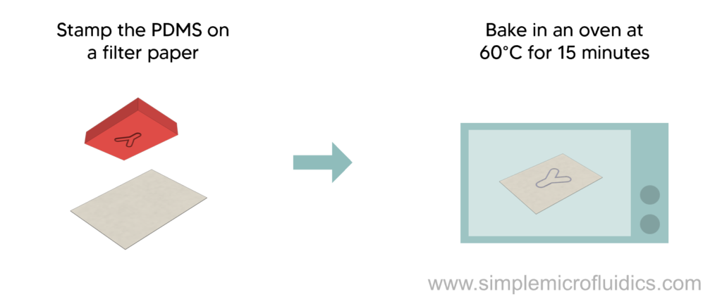
Flash Foam Stamping
Overview
Here is a quick video that might help better understand this technique: link.
This technique uses photosensitive flash foam to create a stamp that selectively absorbs and deposits PDMS on a sheet of filter paper. When the flash foam is exposed to high intensity light, the pores seal themselves creating a non-absorptive area. This is a convenient, quick and easy method compared to wax or inkjet printing.
Technique
Steps
- Design the negative of the circuit in software of your choice.
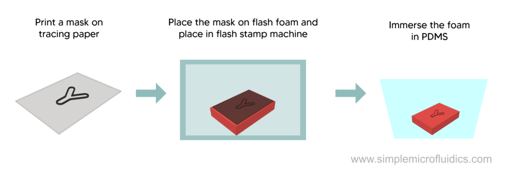
- Print it on a sheet of tracing paper using a normal inkjet printer – black ink should represent the hydrophobic walls of the circuit.
- Place the sheet on flash foam and place them in a flash stamp machine. The xenon tubes will deliver an intense burst of light sealing the exposed areas of the foam.
- Dip the fabricated stamp in PDMS for 15 minutes.
- Transfer the PDMS to a sheet of filter paper by pressing the stamp on it.
- Place the circuit in an oven at 60°C for 15 minutes to cure it.

This technique uses a stamping process to selectively apply a hydrophobic agent to paper to make the circuit.
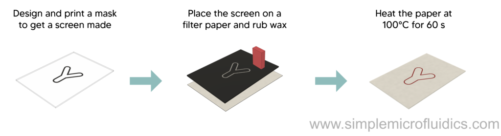
Screen Printing
Overview
This technique utilizes a mesh screen to selectively apply wax to paper to create the boundaries of the fluid channel.
Technique
Steps
- Design a mask using your software of choice
- Print this mask on a transparency sheet using an inkjet printer and get a screen made from a screen printing shop (200 mesh of nylon on an aluminum frame).
- Place the screen on a filter paper sheet and rub solid wax in such a way that it covers the paper on the meshed parts.
- Place the paper on a hot plate at 100°C for 60 seconds to melt and absorb the wax into the paper.
Here are some screen manufactures in USA and UK.


This paper presents a low-cost, simple, and rapid method to fabricate µPADs using screen printing
Laser Printed Polyester Microfluidic Circuits
Overview
This technique uses a toner based printer directly to make microchannels with a depth of ~6 µm.
Technique
Steps:
- Design the circuit in a software of choice. Keep the walls of the channels black as the toner will be printed on the black areas.
- Print the circuit on a transparency sheet with the printer.
- Place another transparency sheet with holes for inlets and outlets on the printed sheet and laminate them together to close the circuit.
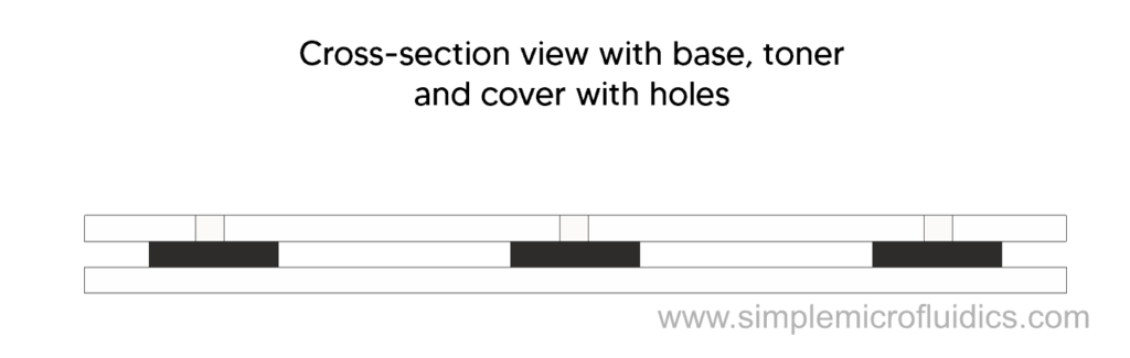
This is a single toner layer method. Double toner layer can also be done to achieve double the thickness and better aspect ratio.
This paper uses a xerographic technique to directly use printed sheets as microfluidic devices.
Embossing
Overview
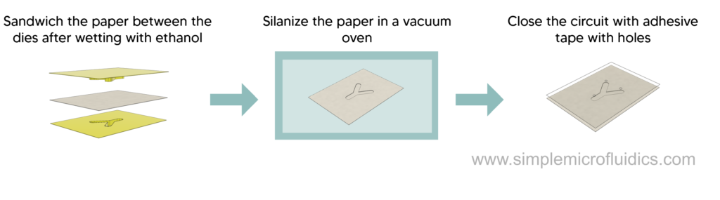
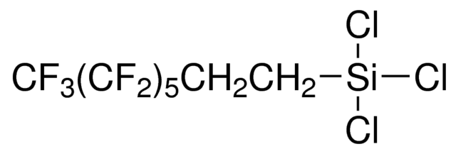
This method uses a 3D printed die to emboss open channels on a sheet of paper that was turned omniphobic by treatment with a highly fluorinated alkylsilane.
Technique
Steps:
- Design the complementary dies in CAD and 3D print them in ABS
- Wet the paper with a few drops of ethanol to increase moldability and reduce the glass transition temperature. It also allows the paper to emboss with less force and avoid tearing at the edges
- Sandwich the paper between the the two dies and apply pressure (0.2 kg/cm²).
- Allow the paper to dry in an oven at 60°C for 30 seconds.
- To make the paper omniphobic, silinize it through a solid vapor-reaction (link)
- Place the paper in a vacuum oven at 95°C and 30 mbar with a solution of RFSiCl3 (10 ml of 30mM in toluene). Let the vapor react with the paper for 5 minutes.
- After the paper is treated, cover the paper with adhesive transparent tape with inlet and outlet holes punched with a laser cutter or a punch.
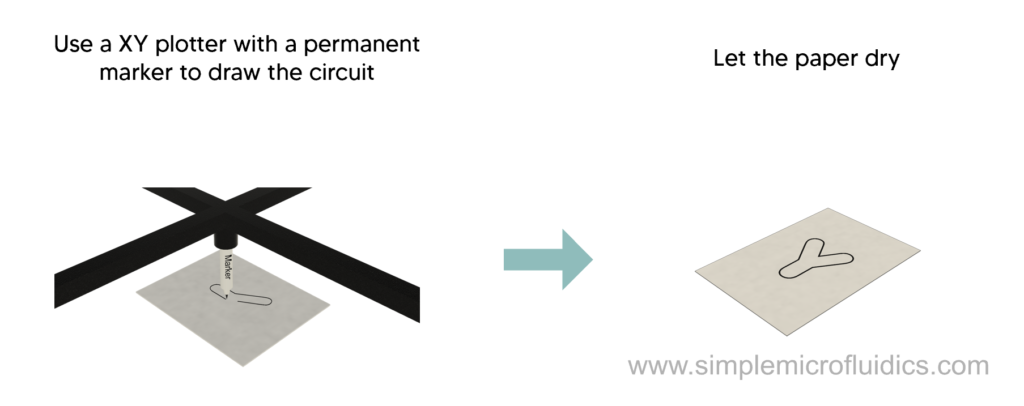
Ink Plotting
Overview
Permanent markers or sharpie have ink that is made of a hydrophobic resin, solvent and colorant. This method uses a common XY plotter to apply this ink to a filter paper with enough pressure that the ink absorbs to the other side of the paper. The solvent evaporates almost instantly leaving behind a hydrophobic resin barrier and colorant.
Technique
Steps:
- Design the circuit using your software of choice – the hydrophobic walls should be filled in with black.
- Place a filter paper in the XY plotter and draw the designed pattern by attaching a sharpie to the plotter (you can also, of course, just do this manually)
- Let the ink dry and the device is ready to use.
This technique uses the hydrophobic resin in permanent marker inks to create microchannels.
Plasma Treatment
Overview
This technique presents a method to make paper microfluidic devices using plasma treatment. The paper is first hydrophobized and then selectively turned hydrophilic with a metal mask through exposure to plasma. Using this method, switches and filters can be directly built into the circuit.
Technique
Steps
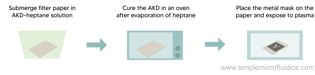
- Dip the filter paper in AKD-heptane solution (0.6 g/L) and immediately remove and leave in a fume cupboard to allow the heptane to evaporate.
- Heat the paper at 100°C for 45 minutes to cure the AKD.
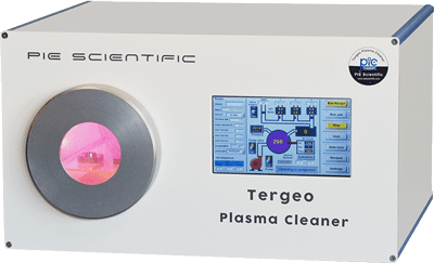
- Sandwich the paper between metal masks with the desired pattern and then place in a vacuum plasma chamber at 15 W for 15 seconds.
The areas exposed to the plasma will turn hydrophilic and form the channels.
The metal stamps are created by mechanically cutting through steel sheets.
Equipment
Fume cupboard (Example)
This paper uses a plasma chamber with a metal mask to selectively turn a hydrophobic sheet hydrophilic.